SONOS 7500/5500 System Basics
User’s Guide System Basics Guide Philips SONOS 7500 Philips SONOS 5500
© 2002 Philips Electronics North America Corporation All rights are reserved. Reproduction in whole or in part is prohibited without the prior written consent of the copyright holder. Publication number M2424-30000-sb-02 Edition 6 Published November, 2002 Printed in U.S.A. Warranty WARNING The information contained in this document is subject to change without notice.
Printing History Edition iv Publication Date Software Revision Edition 1 June 1997 A.0 Edition 2 January 31, 1998 A.1 Edition 3 April 1999 B.0 Edition 4 June 2000 B.1 Edition 5 June 2002 C.0 Edition 6 November 2002 D.0 Revision D.
Revision D.0 ssn February 10, 1999 C:\WINNT\Profiles\dapowell\Desktop\D.0 Books\CD FILES SONOS D.0\System Basics D.0\Frame Files\Front.fm add.
Preface Preface This guide describes the basic operation of the Philips SONOS 7500 and SONOS 5500 ultrasound imaging systems. What’s New In This Guide For D.0 The following major additions, deletions, and changes were made to this guide for software revision D.0: • This manual does not include information about Live 3D and BiPlane imaging modes. For more information about them, see the Using 3-Dimensional and BiPlane Imaging guide.
Preface The SONOS D.0 Documentation Set Use this guide in conjunction with the following books: • Controls Reference—Provides a detailed description of all system controls. • Safety and Standards Guide—Provides information on safety issues. • Measurements and Calculations Reference—Provides information on measurements and calculations that you can perform on your ultrasound system. • Transducer Reference—Provides information on the operation, care, and cleaning of transducers.
Preface viii Revision D.
Contents 1 Contents The System Main Components . . . . . . . . . . . . . . . . . . . . . . . . . . . . . . . . . . . . . . . . . . . . . . . . . . . . . . . . . 1-1 Control Panel . . . . . . . . . . . . . . . . . . . . . . . . . . . . . . . . . . . . . . . . . . . . . . . . . . . . . . . . . . . . . 1-2 Touch Panels. . . . . . . . . . . . . . . . . . . . . . . . . . . . . . . . . . . . . . . . . . . . . . . . . . . . . . . . . . . . . . 1-3 System Power . . . . . . . . . . . . . . . . . . . . . . . . . .
Contents 2 Transducers Introduction . . . . . . . . . . . . . . . . . . . . . . . . . . . . . . . . . . . . . . . . . . . . . . . . . . . . . . . . . . . . . . . 2-1 Connecting Transducers . . . . . . . . . . . . . . . . . . . . . . . . . . . . . . . . . . . . . . . . . . . . . . . . . . . . . 2-2 Imaging Transducers . . . . . . . . . . . . . . . . . . . . . . . . . . . . . . . . . . . . . . . . . . . . . . . . . . . . 2-2 Nonimaging Doppler Pencil Transducers . . . . . . . . . . . . . . . . . . . . . . .
Contents 4 Peripheral Devices Introduction. . . . . . . . . . . . . . . . . . . . . . . . . . . . . . . . . . . . . . . . . . . . . . . . . . . . . . . . . . . . . . . 4-1 System Monitor. . . . . . . . . . . . . . . . . . . . . . . . . . . . . . . . . . . . . . . . . . . . . . . . . . . . . . . . . . . . 4-2 Adjusting the Monitor Position . . . . . . . . . . . . . . . . . . . . . . . . . . . . . . . . . . . . . . . . . . . 4-2 Calibrating the Monitor . . . . . . . . . . . . . . . . . . . . . . . . . . . .
Contents Configuring the RS-232 Interface . . . . . . . . . . . . . . . . . . . . . . . . . . . . . . . . . . . . . . . . . . . . . 4-20 Using the Remote Service Feature . . . . . . . . . . . . . . . . . . . . . . . . . . . . . . . . . . . . . . . . . . . . 4-22 Connecting the Ultrasound System to a Modem . . . . . . . . . . . . . . . . . . . . . . . . . . . . . 4-23 Selecting Remote Service Mode . . . . . . . . . . . . . . . . . . . . . . . . . . . . . . . . . . . . . . . . . .
Contents 6 Doing Exams Introduction. . . . . . . . . . . . . . . . . . . . . . . . . . . . . . . . . . . . . . . . . . . . . . . . . . . . . . . . . . . . . . . 6-1 Selecting a Preset . . . . . . . . . . . . . . . . . . . . . . . . . . . . . . . . . . . . . . . . . . . . . . . . . . . . . . . . . . 6-1 Setting up the Exam . . . . . . . . . . . . . . . . . . . . . . . . . . . . . . . . . . . . . . . . . . . . . . . . . . . . . . . . 6-2 Connecting a Transducer . . . . . . . . . . . . . . . . . . . . . . .
Contents Harmonic Fusion Imaging. . . . . . . . . . . . . . . . . . . . . . . . . . . . . . . . . . . . . . . . . . . . . . . . . . . . 7-8 Introduction . . . . . . . . . . . . . . . . . . . . . . . . . . . . . . . . . . . . . . . . . . . . . . . . . . . . . . . . . . . 7-8 Screen and Touch Panels . . . . . . . . . . . . . . . . . . . . . . . . . . . . . . . . . . . . . . . . . . . . . . . . 7-9 Icons . . . . . . . . . . . . . . . . . . . . . . . . . . . . . . . . . . . . . . . . . . . . . . . . . . . . .
Contents 2D/BMode Imaging . . . . . . . . . . . . . . . . . . . . . . . . . . . . . . . . . . . . . . . . . . . . . . . . . . . . . . . 7-30 Introduction . . . . . . . . . . . . . . . . . . . . . . . . . . . . . . . . . . . . . . . . . . . . . . . . . . . . . . . . . . 7-30 Screen and Touch Panels . . . . . . . . . . . . . . . . . . . . . . . . . . . . . . . . . . . . . . . . . . . . . . . 7-31 Controls . . . . . . . . . . . . . . . . . . . . . . . . . . . . . . . . . . . . . . . . . . . . . . . . . . . .
Contents Color Imaging . . . . . . . . . . . . . . . . . . . . . . . . . . . . . . . . . . . . . . . . . . . . . . . . . . . . . . . . . . . . 7-60 Introduction . . . . . . . . . . . . . . . . . . . . . . . . . . . . . . . . . . . . . . . . . . . . . . . . . . . . . . . . . . 7-60 Screen and Touch Panels . . . . . . . . . . . . . . . . . . . . . . . . . . . . . . . . . . . . . . . . . . . . . . . 7-61 Cardiac. . . . . . . . . . . . . . . . . . . . . . . . . . . . . . . . . . . . . . . . . . . . . . . . . .
Contents Using PW Imaging . . . . . . . . . . . . . . . . . . . . . . . . . . . . . . . . . . . . . . . . . . . . . . . . . . . . 7-93 Auto Trace in PW (noncardiac) . . . . . . . . . . . . . . . . . . . . . . . . . . . . . . . . . . . 7-95 Nonimaging PW . . . . . . . . . . . . . . . . . . . . . . . . . . . . . . . . . . . . . . . . . . . . . . . 7-97 Using Triplex Doppler in PW imaging . . . . . . . . . . . . . . . . . . . . . . . . . . . . . . 7-99 Using CW imaging . . . . . . . . . . . . . . . . . . . .
Contents 8 Annotation Introduction . . . . . . . . . . . . . . . . . . . . . . . . . . . . . . . . . . . . . . . . . . . . . . . . . . . . . . . . . . . . . . . 8-1 Screen and Touch Panels. . . . . . . . . . . . . . . . . . . . . . . . . . . . . . . . . . . . . . . . . . . . . . . . . . . . . 8-2 Controls . . . . . . . . . . . . . . . . . . . . . . . . . . . . . . . . . . . . . . . . . . . . . . . . . . . . . . . . . . . . . . . . . . 8-3 Annotation Procedure . . . . . . . . . . . . . . . . . . . . . . .
Contents 9 Measurements Introduction. . . . . . . . . . . . . . . . . . . . . . . . . . . . . . . . . . . . . . . . . . . . . . . . . . . . . . . . . . . . . . . 9-1 Screen and Touch Panels . . . . . . . . . . . . . . . . . . . . . . . . . . . . . . . . . . . . . . . . . . . . . . . . . . . . 9-1 Controls. . . . . . . . . . . . . . . . . . . . . . . . . . . . . . . . . . . . . . . . . . . . . . . . . . . . . . . . . . . . . . . . . . 9-2 Cardiac Primary . . . . . . . . . . . . . . . . . . . . . . . . . .
Contents 10 Analysis Introduction . . . . . . . . . . . . . . . . . . . . . . . . . . . . . . . . . . . . . . . . . . . . . . . . . . . . . . . . . . . . . . 10-1 Screen and Touch Panels. . . . . . . . . . . . . . . . . . . . . . . . . . . . . . . . . . . . . . . . . . . . . . . . . . . . 10-2 Controls . . . . . . . . . . . . . . . . . . . . . . . . . . . . . . . . . . . . . . . . . . . . . . . . . . . . . . . . . . . . . . . . . 10-3 Primary . . . . . . . . . . . . . . . . . . . . . . . . . . . . . . . .
Contents 11 Loops Introduction. . . . . . . . . . . . . . . . . . . . . . . . . . . . . . . . . . . . . . . . . . . . . . . . . . . . . . . . . . . . . . 11-1 Screen and Touch Panels . . . . . . . . . . . . . . . . . . . . . . . . . . . . . . . . . . . . . . . . . . . . . . . . . . . 11-2 Controls. . . . . . . . . . . . . . . . . . . . . . . . . . . . . . . . . . . . . . . . . . . . . . . . . . . . . . . . . . . . . . . . . 11-3 Primary . . . . . . . . . . . . . . . . . . . . . . . . . . . . . . . . . . .
Contents 12 Disk Introduction . . . . . . . . . . . . . . . . . . . . . . . . . . . . . . . . . . . . . . . . . . . . . . . . . . . . . . . . . . . . . . 12-1 Screen and Touch Panels. . . . . . . . . . . . . . . . . . . . . . . . . . . . . . . . . . . . . . . . . . . . . . . . . . . . 12-2 Controls . . . . . . . . . . . . . . . . . . . . . . . . . . . . . . . . . . . . . . . . . . . . . . . . . . . . . . . . . . . . . . . . . 12-3 Primary . . . . . . . . . . . . . . . . . . . . . . . . . . . . . . . . . .
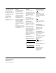
1 The System Main Components Transducer holders Tilt and swivel monitor Optical disk drive Service floppy disk drive Optional VCR Touch panels Keyboard controls Transducer connections Circuit breaker (on back) Main power switch Optional peripheral Live-3D or IDI PC or other peripheral Wheel lock 6apc0147 Revision D.0 1-1 January 28, ssn February 10,1999 1999 C:\WINNT\Profiles\dapowell\Desktop\D.0 Books\CD FILES SONOS D.0\System Basics D.0\Frame Files\1CH.FM add.
The System Control Panel Control Panel Touch panels contain most of the controls Volume control Mic Volume Reset Test Setup Gain Patient ID Alphanumeric keyboard and function keys 1 Tab 2 Q Cps Lck 3 W A Shift 4 E S Z 5 R D X 6 T F C 7 Y G V LGC 8 U H B I J N O K M - 0 9 , .
The System Touch Panels Touch Panels When you touch a control, the system highlights it to indicate the control is active. System controls, such as Presets, Tools, Physio, and Probes are located on the left touch panel. Imaging modalities, such as 2D, MMode, Color, PW, CW, and Angio appear on the primary right touch panel. Additional touch and rotary controls pertaining to the selected modality also appear on the primary right touch panel.
The System Touch Panels Left Touch Panel Contains system-specific controls. Right Touch Panel Contains mode-specific controls. Secondary Controls Each rotary control adjusts the highlighted control above it. To change the value displayed, turn the rotary control to the right or left. 1-4 Secondary Touch Panel Contains less frequently used controls. Secondary Controls Revision D.
The System System Power System Power All systems have a separate circuit-breaker switch on the back panel, near the power-cord connection. This switch has on and off settings. If the SONOS system does not power up when the main power switch is turned on, this circuit-breaker may have tripped or may be set to off. If this happens, turn the circuit breaker completely off and then back on. Then turn system power on using the main power switch.
The System System Power NOTE Turning the main power switch back on before the shutdown message is displayed stops the shutdown procedure. The system and PC remain on. NOTE After the shutdown message has displayed, the system ignores further changes to the main power-switch setting, and shutdown completes. However, if you change the power-switch setting after the shutdown message is displayed, the new setting takes over after shutdown.
The System Setting Up the System Setting Up the System 1. Press Setup . Setup 2. Touch System. System 3. Perform Setup tasks described in the following sections. Revision D.0 ssn February 10, 1999 C:\WINNT\Profiles\dapowell\Desktop\D.0 Books\CD FILES SONOS D.0\System Basics D.0\Frame Files\1CH.FM add.
The System Setting Up the System Entering Your Institution Name 1. Touch Institute Name. System Institute Name 2. Type the name of your institution. You can type up to 32 characters on two lines. If you make a mistake, use to erase the previous characters. 3. When you are done, press highlight Okay and press Enter Enter twice quickly, or with the trackball, . Enter 1-8 Revision D.
The System Setting Up the System Setting the Date 1. Turn the Year rotary control to the right to increase the year setting, or to the left to decrease it. System Year 1999 2. Turn the Month rotary control to the right to select a month later in the year, or to the left to select an earlier month. System Month May 3. Turn the Day rotary control to the right to increase the day of the month, or to the left to decrease it. System Day 19 Revision D.
The System Setting Up the System Setting the Time 1. Turn the Hour rotary control to the right to increase the hour setting, or to the left to decrease it. The system uses a 24-hour format. System Hour 13 2. Turn the Minute rotary control to the right to increase the minutes setting, or to the left to decrease it. System Minute 58 1-10 Revision D.
The System Setting Up the System Adjusting the Control Panel and Touch Panel Lighting Tip: Keep the Touch Light setting as low as possible for the ambient light. 1. To adjust the lighting of the touch controls, touch the Touch Light control and turn the Touch Light rotary control to the right to brighten the touch controls, or to the left to dim them. System Touch Light 6 2.
The System Setting Up the System Adjusting the Monitor Position You can move the monitor up and down to find the position that is most comfortable for you. CAUTION 1-12 Do not push the release bar under the center front of the monitor unless you want to take the monitor off its base. See the Safety and Standards Guide for information on removing the monitor and moving the system. Revision D.
The System Setting Up the System Calibrating the Monitor CAUTION You must calibrate the monitor lighting correctly, or improper adjustment of system controls can occur. This can result in poor real-time image quality, VCR recording quality, or print quality. There are two versions of SONOS monitor. You calibrate one using brightness/ contrast dials. You calibrate the other using brightness/contrast push buttons.
The System Setting Up the System 2. On the monitor, turn the brightness dial down just until the bottom grayscale bar (the 16th bar) looks pure black and disappears into the screen background. When the monitor is properly calibrated, 15 grayscale bars are visible, running from white (top) to nearly black (bottom). 6apc0158 NOTE While not a direct danger to patient or operator safety, ambient magnetic fields may affect the colors that are displayed on the imaging screen.
The System Setting Up the System 2. On the monitor, press and hold the left brightness button only until the bottom grayscale bar (the 16th bar) looks pure black and disappears into the screen background. When the monitor is properly calibrated, 15 grayscale bars are visible, running from white (top) to nearly black (bottom). - NOTE + - + While not a direct danger to patient or operator safety, ambient magnetic fields may affect the colors that are displayed on the imaging screen.
The System Using the Foot Switch Using the Foot Switch If you are using the foot switch, plug it into the back of the system into the connector labelled Foot Switch. Use the foot switch as follows: • Left pedal to freeze • Middle pedal to print • Right pedal to tape See Using 3-Dimensional and BiPlane Imaging Guide for information about using the foot switch to acquire Full Volume images in Live-3D mode.
The System Supplies and Accessories Supplies and Accessories To order supplies and accessories from within the U.S.A., visit: http://shop.medical.philips.com or call Medical Supplies at 1-800-225-0230. From other countries, contact your local Philips representative or sales office. Revision D.0 ssn February 10, 1999 C:\WINNT\Profiles\dapowell\Desktop\D.0 Books\CD FILES SONOS D.0\System Basics D.0\Frame Files\1CH.FM add.
The System Supplies and Accessories 1-18 Revision D.
2 Transducers Introduction This chapter provides information about NOTE • Connecting transducers (page 2-2) • Activating transducers (page 2-4) • Disconnecting and storing transducers (page 2-5) • Troubleshooting transducers (page 2-6) Be sure that you use only Philips-approved transducers for your ultrasound system.
Transducers Connecting Transducers Connecting Transducers Imaging Transducers 1. With the latch in the vertical position, insert the transducer connector. Never force a transducer into place. If you feel any resistance, check the pin positions and try reinserting it. T4 T2 T1 T3 Vertical 6apc0148 2. Lock the connector by flipping the transducer lever to horizontal. T4 T1 T2 T3 Horizontal 2-2 Revision D.
Transducers Connecting Transducers Nonimaging Doppler Pencil Transducers 1. Align the connector’s prongs with the receptacle. T4 T2 T1 T3 6apc0149 2. Insert the connector. T4 T1 T2 T3 6apc0148 Revision D.0 ssn February 10, 1999 C:\WINNT\Profiles\dapowell\Desktop\D.
Transducers Activating Transducers Activating Transducers 1. Touch Probe. Probe 2. Touch the control indicating where the transducer is connected. Probe Left Center Right Nonimage 2-4 Revision D.
Transducers Disconnecting and Storing Transducers Disconnecting and Storing Transducers 1. Unlock and remove the transducer. T4 T1 T2 T3 Unlocked 6apc0148 2. Store external imaging transducers in the holders. Place connectors in the individual side pockets to protect the pins. Store TEE transducers on a wall-mounted rack. b 02 10 Fe :07 9 :1 4 1 ren’s Child Transducer holder 300e008a NOTE See the Transducer Reference for information on caring for and cleaning your transducer. Revision D.
Transducers Transducer Troubleshooting Transducer Troubleshooting Always make sure that the active preset is appropriate for the study being performed. Symptoms Suggestions No Probe or ?? Probe is displayed on the imaging screen. Place the transducer connector lock in the horizontal position. No image. Select the transducer on the touch panel (Left, Center, Right, or Nonimage, under Probe).
Transducers Transducer Troubleshooting NOTE Symptoms Suggestions Need better penetration. Use the lower Frequency Fusion setting. Otherwise, change to a lower frequency transducer. Use the LVO1 or TCE1 setting if you are in Contrast Harmonic imaging, and the Frequency Fusion 1 setting if you are in Harmonic Fusion imaging. Linear transducer loses part of image. Make sure gel completely covers the face of the transducer.
Transducers Transducer Troubleshooting 2-8 Revision D.
3 Presets Introduction Tip: To remove the preset name from the screen, touch Preset and Preset Name on the left touch panel. A preset is a group of specific control settings that optimize the system for the exam you are about to perform. You use presets to establish initial settings such as compression and gain values, color maps and processes, screen formats, and acoustic power output levels.
Presets Philips-Defined Presets Philips-Defined Presets The system ships with Philips-defined presets for each exam type. Table 3-1 shows the number of Philips-defined presets by exam type and the number of presets you can create.
Presets Choosing Presets Choosing Presets 1. Touch Preset. Preset 2. Touch the exam type (if applicable). Preset Cardiac Exam 3. Touch the preset you want to use for this study. Preset Cardiac Exam Dr. R Revision D.0 ssn February 10, 1999 C:\WINNT\Profiles\dapowell\Desktop\D.0 Books\CD FILES SONOS D.0\System Basics D.0\Frame Files\3CH.FM add.
Presets Modifying Presets Modifying Presets Tip: If you modify a Philips preset, you need to save it as a new preset. 1. Touch the preset you want to alter. You can modify all Philips and custom presets. Preset Cardiac Exam Dr. R. 2. Adjust controls to display the image as you want to see it. Gain Compress 3-4 Depth Revision D.
Presets Modifying Presets Tip: Be sure the Annotation labels and Analysis measurements and calculations are appropriate for the new preset. For more information see Chapter 8, Chapter 9, and Chapter 10. 3. To change Setup values, such as lighting and display options, press Setup and make the necessary adjustments. Press Setup again to exit Setup mode. Setup 4. With Preset active, touch Save Preset. Preset Save Preset 5. Select Modify Current with the trackball and press Enter .
Presets Creating Presets Creating Presets You can define your own presets for each exam type and are only limited by the amount of available space on the touch panel. To create a new preset, use the following procedure: 1. Touch Preset. Preset Cardiac Exam 2. Vascular Exam Touch a preset of the same exam type as the one you want to create. This ensures that most system settings, including annotation labels and analysis measurements, are appropriate for the new preset.
Presets Creating Presets 3. Adjust the controls to display the image as you want to see it. To change Setup values, such as lighting and display options, press Setup and make the necessary adjustments. Press Setup again. 4. Touch Save Preset. Preset Save Preset 5. Highlight Create New with the trackball and press Enter . You are prompted to name the new preset. Give the preset a unique name and quickly press Enter twice or select Okay and press Enter .
Presets Storing Presets Storing Presets You can store modified or newly created presets, and are only limited by the amount of available space on the touch panel. To store a modified or new preset, use the following procedure: 1. After you have finished modifying or creating a preset to your satisfaction (as described on page 3-4 or page 3-6), with Preset active, touch Save Preset.
Presets Copying Presets to a Different SONOS System Copying Presets to a Different SONOS System To copy presets from one SONOS system to another, do the following: 1. On the system that is currently using the preset, store the preset on a floppy diskette using the Backup Preset control. 2. Insert the diskette in the SONOS system that you want to upgrade. 3. Touch Add Preset (which is below Restore Preset on the touch panel). This adds all presets from the disk to the system’s current presets.
Presets Deleting Presets Deleting Presets If the preset memory is full, you may have to delete a preset before creating new ones. You cannot delete Philips presets, but you can delete customized presets. 1. Touch the preset you want to delete. Preset Cardiac Exam Dr. R 2. Touch Delete Preset. Preset Cardiac Exam Delete Preset 3. To confirm the deletion, highlight Okay with the trackball and press Enter . To retain it, highlight Cancel and press Enter .
4 Peripheral Devices Introduction WARNING This system has been investigated to the requirements of IEC 601-1, with peripherals that are powered by the built-in isolation transformer. Anyone who uses the system with peripherals that are powered from a separate wall receptacle is considered to be configuring a medical system, and is therefore responsible that the system complies with the requirements of the IEC 601-1-1. If you have additional questions, contact your Philips representative.
Peripheral Devices System Monitor System Monitor Adjusting the Monitor Position For information about adjusting the system monitor for user comfort, see “Adjusting the Monitor Position” on page 1-12. Calibrating the Monitor There are two versions of the SONOS monitor. You calibrate one using brightness/contrast dials. You calibrate the other using brightness/contrast push buttons. For instructions, see “Calibrating the Monitor” on page 1-13. 4-2 Revision D.
Peripheral Devices Floppy Drive Floppy Drive The Service Floppy drive allows you to • Save and restore customized presets • Format and erase floppy diskettes • Upgrade software • Install software options Controls Add Preset Reads a previously stored system configuration data set from disk. Backup Preset Saves system configurations, including presets and other settings, to a formatted floppy diskette. Screen instructions are provided. Clear Diskette Erases all disk files.
Peripheral Devices Floppy Drive Accessing the Service Floppy Disk Drive 1. Press Setup . Setup 2. Touch Service Floppy. Service Floppy 3. Select the option you want and follow the instructions. Press return to imaging. Setup to Service Floppy Format Clear Read Backup Restore Diskette Diskette Diskette Preset Preset Upgrade Install Software Options 4-4 Add Preset Revision D.
Peripheral Devices Optical Disk Drive Optical Disk Drive Tip: Older SONOS systems may not be able to read data stored by newer SONOS systems on newer optical disks. 5 1/4-inch The following table describes the optical-disk media that can be used with the SONOS system using a 5 1/4-inch optical-disk drive: Media Compatibility and Capacity Drive Revision 4X SONOS 7500/5500 A.0 through B.0 1X (read only) 600 MB 2X (read/write) 1.2 GB 4X (read/write) 2.3 GB 8X SONOS 7500/5500 B.1 through D.
Peripheral Devices PC PC A PC is installed on systems that receive the optional Live-3D imaging software. This PC allows users to perform the following Live-3D operations: • Save study images to the PC disk. • Review, retrieve, and delete studies that are stored on the PC disk. • Export studies from the PC disk to the CD-ROM media. For more information about these operations and about the PC’s controls, see the Using 3-Dimensional and BiPlane Imaging Guide.
Peripheral Devices VCR PAUSE Pauses and resumes recording or playback, without disengaging the VCR heads. PLAY Activates VCR playback. RECORD Indicates that the system is recording the display onto a VCR tape. REW Rapidly rewinds a VCR tape. SEARCH Pauses the VCR playback picture and puts the system into search mode. Speed Adjusts the tape search speed. Available when SEARCH is on. STOP Stops any active VCR operation. Tape Starts and pauses VCR recording.
Peripheral Devices VCR Setup Blink, Normal, and Inverse are available for both Tape Number and Tape Time. With VCR highlighted, press Setup and select either Tape Number or Tape Time. Turn the rotary control beneath the highlighted selection to select Blink, Normal, or Inverse. Press Setup again to return to imaging. 4-8 Blink Displays tape time or tape number in blinking numerics. Inverse Displays tape time or tape number in numerics within a shaded box.
Peripheral Devices VCR VCR Troubleshooting Tip: Always use high quality tapes for best results. Symptoms Suggestions Tape controls do not display. Make sure there is a tape in the VCR. Cannot hear sounds on the tape. Turn up the Volume control. Images are too light or dark on playback. Make sure the monitor and controls are correctly set. See “Calibrating the Monitor” on page 1-13 for details. For tapes recorded with color, adjust Color during playback. Playback quality is inferior.
Peripheral Devices Printers Printers The SONOS system allows you to send an image to your local printer or to a networked DICOM printer. NOTE The DICOM Print support option must be installed by your Philips Customer Engineer. The ultrasound system must include an Integrated Digital Interface (IDI) configured for DICOM networking. The system must also be configured for DICOM printers. Printing an Image Locally Use the following procedure to print using the SONOS printer. 1.
Peripheral Devices Printers Tip: If Quad Format is on in Setup, you must 2. Press Print . press Print four times to produce a four-image print. Print Revision D.0 ssn February 10, 1999 C:\WINNT\Profiles\dapowell\Desktop\D.
Peripheral Devices Printers DICOM Printers DICOM print allows you to print ultrasound still frames to a networked DICOM black and white or color printer. Images are automatically sent to the printer when the study ends. When Network Autosend is enabled, a sheet of images is printed when the sheet is full. If both color and black and white DICOM printers are configured, the system can automatically send images to the appropriate printer.
Peripheral Devices Printers If the system is configured for both a color and a black and white DICOM printer, the DICOM rotary control choices are Tip: The settings that you select must match the settings of the output device (external printer) that you want to use. • Off—Disables DICOM print. • Auto—The system sends acquired images to one of the DICOM printers, depending on the image type. - Monochrome images go to the DICOM black and white printer.
Peripheral Devices Printers Using DICOM Prints Acquiring Images When DICOM print is enabled, pressing Acquire or touching Acquire Frame when a still frame is displayed places the current image in the queue for DICOM print. A print exposure indicator window is displayed for four seconds, at the bottom right of the imaging screen. If Network Autosend is on, SONOS sends a preselected number of images to the printer. The images begin printing as soon as the printer has received the specified number of images.
Peripheral Devices Printers Retrieving Stored Images for DICOM Printing Images stored on the system’s hard disk or optical disk can be queued for DICOM printing by using the Disk Retrieve control in Loop mode. After Disk Retrieve loads an image into system memory, it can be printed to the DICOM printer when the current study ends, provided the DICOM rotary control is enabled. 1 Touch Disk on the left touch panel. 2 Touch End Study on the left touch panel. 3 The system a.
Peripheral Devices Printers Selecting a Different Printer Use the following procedure to select the print device. 1. Press Setup , and touch Print. Print Tip: If External appears on the screen, you can connect an external printer to the system. 2. Adjust controls to change where black and white, color, VCR, Report, or Serial Port pages are printed. Print B/W Color VCR Report DICOM UP-910 UP-5200 UP-5200 UP-910 B/W 3. 4-16 Press Setup to exit Setup mode. Revision D.
Peripheral Devices Printers Printing an Analysis Report After you complete configuring the RS232 interface, you can send analysis reports to an external printer or to a PC. 1. Touch Analysis. Analysis 2. 2D Touch Report. Analysis Results Report Box 3. Press Print . Revision D.0 ssn February 10, 1999 C:\WINNT\Profiles\dapowell\Desktop\D.
Peripheral Devices Printers Printer Troubleshooting Tip: Always use high quality paper for best results. Symptoms Suggestions Paper jams during printing. Fan the paper before loading it. Store paper flat. If it is curled, try to flatten it before loading. Make sure paper trays fit securely into the printer. 4-18 Prints have white lines. Check the paper supply and remove any pieces with gel on them. Always clean gel off your hands before loading paper. Four images print instead of one on a sheet.
Peripheral Devices Printers Symptoms Suggestions The colors do not look right. Press Setup , touch Print, touch UP-5xxx Adjust (control name depends on printer), and alter the settings, as necessary. The default values for the UP-5200 are • Contrast – 6 • Brightness – 4 • Red, Green, Blue – 12 The default values for the UP-5600 are Black and white contrast or brightness is not ideal.
Peripheral Devices Configuring the RS-232 Interface Configuring the RS-232 Interface You can configure the RS-232 interface for sending analysis reports to either an external printer or a PC. The RS-232 interface is a 25-pin connector port located on the back of the ultrasound system (J1). See “Connecting the Ultrasound System to a Modem” on page 4-23. 1. Press Setup , and touch System. System 2. Touch Serial Port. Serial Port 4-20 Revision D.
Peripheral Devices Configuring the RS-232 Interface 3. Use the trackball to highlight a setting, and make your selections by typing in the information. On the Serial Port Setup window, enter data such as baud rate, stop and data bits, and select parity and print range according to the external printer device that is connected. Serial Port Setup Baud Rate: 9600 Stop Bits: 1 Data Bits: 8 Timeout Duration: 30 4.
Peripheral Devices Using the Remote Service Feature Using the Remote Service Feature This option may or may not be available in your local area. For details, contact your Philips Service Representative. WARNING 4-22 The Remote Service feature gives your Philips Service Representative access to the system via a modem. This section describes how to use the Remote Service feature. DO NOT use the Remote Service feature or the modem while imaging a patient. Revision D.
Peripheral Devices Using the Remote Service Feature Connecting the Ultrasound System to a Modem 1. Disconnect all transducers and other external peripherals. 2. Connect the modem to the RS-232C 25-pin connector port located on the back of the ultrasound system (J1).
Peripheral Devices Using the Remote Service Feature Selecting Remote Service Mode 1. To access the Test Menu, press RESET 2. TEST Test . SETUP Use the trackball to select Remote Service Mode and press Enter . Test Menu Run Basic Test Run Extended Basic Key PRocessor Scan Converter Scanner Other Tests and Utilities Test Setup Run Time Error Log System Information Remote Service Mode RST Error Log To return to Imaging mode, press 3. Test .
Peripheral Devices Using the Remote Service Feature Note that the information in the Status box is not an indicator that the Philips Representative is done working on the system. While the system is being worked on, the Status box is updated: Idle Indicates the system is not logged on to remote service. Remote User Connected Indicates the Service Center is connected to the system. Working Indicates the system is logged on to remote service, and is being worked on.
Peripheral Devices Using the Remote Service Feature 4 To exit from the Test Menu and return to Imaging mode, press Test . Test Menu Run Basic Test Run Extended Basic Key PRocessor Scan Converter Scanner Other Tests and Utilities Test Setup Run Time Error Log System Information Remote Service Mode RST Error Log To return to Imaging mode, press 5 WARNING 4-26 Test . To return to live imaging, touch 2D or another imaging mode.
5 Physios Introduction Using SONOS physios, you can connect ECG and other physical sensors to the patient and monitor their heart sounds, pulse, respiration, and ECG waveforms in real time. This chapter provides information about • Physio imaging screen and touch panels (page 5-2) • Physio controls (page 5-3) • Setting up physios (page 5-7) • Setting up triggering modes (page 5-8) • Connecting physios (page 5-10) • Viewing physios (page 5-12) • Physio troubleshooting (page 5-14) Revision D.
Physios Screen and Touch Panels Screen and Touch Panels Heart sound waveform Pulse waveform Respiration waveform ECG waveform 300e050 PW Physio Rwave Beep ECG Resp 5-2 Delay 15 Hrtsound Physio Suppress Invert Trigger ECG Pulse Beats 2 Test ECG ECG Gain 40% Position Revision D.
Physios Controls Controls Primary Beats When Trigger ECG is active, adjusts the number of beats between the triggered updates of a 2D, Color, Angio, or Spectral Doppler image. AutoBeat Sequence Defines the sequencing of R-wave acquisition of images in Triggering mode. Delay When Trigger ECG is active, updates the 2D, Color, Angio, or spectral Doppler image at a specified number of milliseconds after the R-wave. ECG Enables gain and position adjustment of the ECG waveform.
Physios Controls Tip: To suppress the ECG waveform, you must turn ECG off in Physio Setup. 5-4 Physio Suppress Turns Hrtsound, Pulse, and Resp physio waveforms on or off. Position [Position ECG, Position Pulse, Position Resp or Position Hrtsound] Adjusts the vertical position of the active waveform. Available in MMode, spectral CW and PW, and when Acoustic Quantification (AQ) waveforms are displayed. Pulse Enables gain and position of the pulse waveform. Available in Color mode and Spectral Doppler.
Physios Controls Trigger Selects the triggering mode: Off, ECG, Timer, Loop/ ECG or Loop/Timr. Trigger activates either Beats and Delay or time Interval for triggering 2D, Color, Angio, or Doppler (with or without spectral) updates. Loop/ECG and Loop/Timr are available in Contrast or AD only. With Contrast active, Loop/ECG lets you acquire the same portion of the cardiac cycle while the 2D, Color, or Angio image is displayed in real time.
Physios Controls Setup ECG Selects an input source for the ECG waveform, or turns the waveform off. ECG Output Lets you take the ECG signal from the ECG output on the back of the system and use the signal as input to another device. Filter Removes frequencies below the hertz level specified. Only available when Hrtsound Normal is activated. Hrtsound Selects an input source for the heart sound waveform, or turns the waveform off.
Physios Setting Up Physios Setting Up Physios 1. Press Setup , and touch Physio. Physio 2. Turn the rotary controls to adjust the Physios setup for the waveforms you want to view, or turn the rotary control to Off for those that you do not need. Turn Normal to obtain the signal from a physio transducer connected to the system, or AUX for an auxiliary signal from another source. Physio Resp Pulse Hrtsound ECG Normal Normal Aux 3 Normal 3. Press Setup to exit Setup mode. Revision D.
Physios Setting Up Triggering Modes Setting Up Triggering Modes 1. Touch Physio. 2. Use the Trigger rotary control to select ECG, Timer, Loop/ECG, or Loop/Timr mode. (Loop/ECG and Loop/Timr only appear if Contrast or AD is on. For complete details, see Using Contrast Imaging). 2D Physio ECG Physio Suppress Test Trigger ECG Tip: To retain Trigger Beats, Delay, and Interval settings, save them to a preset. Triggering presets depend on study type and imaging mode. 3.
Physios Setting Up Triggering Modes Tip: Triggered images can only be acquired in Contrast and AD modes. 4. Turn the Trigger rotary control to Loop/ECG or Loop/Timr in Contrast or AD mode, to view a real-time image and acquire triggered images. Physio 2D Trigger Delay Beats ECG 2 Loop/ ECG 5 Gain 16% 5. Turn the Trigger rotary control to Trigger ECG in Contrast mode. The Frames control appears and the system goes into Multiple Frame Triggering mode (MFT).
Physios Connecting Physios Connecting Physios NOTE Your system may not have all of the physios shown. 1. Make sure that ECG Normal is displayed in Setup. Insert the ECG cable connector into the ECG receptacle under the keyboard. ECG ECG AUX HEART RESP PULSE SOUND PATIENT CONNECTION ELECTRICALLY ISOLATED 300e003a 2. Connect the pin connector to the ECG cable. Left Arm Right Arm Left Leg 5-10 Revision D.
Physios Connecting Physios 3. Attach the electrodes and ECG leads to the patient as shown. Proper ECG lead placement is critical for receiving a good ECG and respiration signal. Right Arm Left Arm Left Leg NOTE Lead placements in the drawing above are anatomically incorrect; however, this placement obtains optimal triggering for AQ, CK, AD, and 3D. 4. Connect and attach cables for other physios you want to use. Make sure Setup values match the connections.
Physios Viewing Physios Viewing Physios NOTE The Pulse waveform is unavailable in 2D, Color, Angio, nonspectral Doppler modes, and AQ. 1. Touch Physio. Only waveforms that you have set up appear. Physio Suppress must be off to see all available waveforms. Physio 2. Verify that the ECG complex size is correct for each mode by touching the mode (2D, MMode, PW, CW, or AQ) and ECG. To set the size of an active trace, adjust the Gain rotary control. 2D ECG ECG Gain 16% 5-12 Revision D.
Physios Viewing Physios 3. Check the trace positions by touching each mode and then each waveform you want to see in that mode. Only one waveform control can be active at a time. The Gain and the Position rotary controls pertain to the active waveform. If an active Trace is not displayed, touch Test. If necessary, adjust Position. Physio ECG MMode Resp Pulse Hrtsound Test ECG ECG Gain 16% Position Revision D.0 ssn February 10, 1999 C:\WINNT\Profiles\dapowell\Desktop\D.
Physios Physio Troubleshooting Physio Troubleshooting Always make sure that the active preset is appropriate for the study being performed. Symptoms Suggestions Physio does not display. For physios other than ECG, make sure Physio Suppress is off. Check to ensure the physio cable is secure in the correct connection and is correctly attached to the patient. Touch Test to test physio signals.
Physios Physio Troubleshooting Symptoms Suggestions 2D reference image does not update Make sure 2D Hold or BMode Hold is off in CW and PW modes. Verify that Freeze is off. Verify that the ECG leads are connected properly. Adjust Delay or Beats rotary control if an R-wave is present, or Interval rotary control if there is no R-wave (all Physio Trigger controls). Adjust ECG Gain rotary control. System does not stop beeping Touch RWave Beep to turn off the beep during each R-wave.
Physios Physio Troubleshooting 5-16 Revision D.
6 Doing Exams Introduction This chapter outlines the basic steps for performing an ultrasound imaging exam. The basic procedure is to: • Select a preset (page 6-1) • Set up the exam (page 6-2) • Connect a transducer (page 6-10) • Optimize the image (page 6-10) • Videotape the exam (page 6-11) • Store the image (page 6-15) • Send the image over a network (if desired) (page 6-15) The following sections walk you through this procedure.
Doing Exams Setting up the Exam Setting up the Exam 1. NOTE Make sure all peripherals are on and the recording medium is correctly inserted. You can operate the VCR using the controls on the touch panel. See Chapter 4 for more information. 2. Select or reselect the preset to match the study you are about to perform. The active preset is shown on the screen, unless you touch Preset Name on the left touch panel to turn off the preset display. Preset Cardiac Exam Dr. R. 6-2 Revision D.
Doing Exams Setting up the Exam 3. Press Patient ID to display the Patient Information window. The window is preset-dependent. It contains information pertinent to the exam type. Patient ID Enter NOTE Patient information is automatically stored to the Analysis report, and can only be edited on the Patient Information window. Revision D.0 ssn February 10, 1999 C:\WINNT\Profiles\dapowell\Desktop\D.
Doing Exams Setting up the Exam 4. To enter new patient data: a. If a PATIENT SELECTION window is onscreen, highlight Manual Entry and press Enter . b. Highlight New and press c. Type in the new patient information. A red box outlines the active field. To move from field to field, use the trackball. Enter . Note: The MRN is the Medical Record Number.
Doing Exams Setting up the Exam 5. To edit patient data, highlight Edit and press Patient Information New Enter . Type in your changes. Current Date mm/dd/yyyy Edit Reset Prior Last Name: First/Middle: MRN: DOB: Accession: Sex: Misc: MM/DD/YYYY M F Location: Physician: Performed by: Height: cm inches Weight: kg lbs BSA via Weight only Indication: NOTE The current date shows the system setup date; see Chapter 1 for details.
Doing Exams Setting up the Exam 6. To enter this patient information and return to live imaging, press Enter twice, or press Patient ID . Patient ID Enter 6-6 Revision D.
Doing Exams Setting up the Exam 7. To specify the information that will appear on the screen, press Setup . Then touch System on the right touch panel and ID Display. Use the trackball to select the patient identification information that will be displayed on the screen. Note: The Misc field matches the Misc field on the Patient Information window. SETUP: Modify controls. Press to return to imaging. Patient ID Display Select the text that you want displayed on the images.
Doing Exams Setting up the Exam 8. Touch the mode you want to use. (If a noncardiac preset is active, the BMode touch control appears instead of the 2D touch control.) 2D MMode Color PW CW Angio AQ 6-8 Revision D.
Doing Exams Setting up the Exam 9. Touch any of the mode-specific controls that are displayed. See the section on the mode you are using for detailed information. 2D MMode Color PW CW Angio AQ 10. Adjust imaging controls applicable to this mode, as necessary. General imaging controls are described in Chapter 7 Gain Compress Depth Revision D.0 ssn February 10, 1999 C:\WINNT\Profiles\dapowell\Desktop\D.
Doing Exams Connecting a Transducer Connecting a Transducer For information about connecting transducers and physio sensors to the SONOS system, see Chapter 2 and Chapter 5. Optimizing the Image For information about optimizing images, see the specific imaging-modality sections in Chapter 7. 6-10 Revision D.
Doing Exams Videotaping the Exam Videotaping the Exam Tip: The tape icon appears on the imaging screen when a tape is in the VCR. 1. Make sure the VCR is on, and that a tape is in. To record time or frame numbers, touch Tape Time or Tape Number (only one appears, depending on what you select in Setup.) 2. To begin taping, press Tape . Tape Revision D.0 ssn February 10, 1999 C:\WINNT\Profiles\dapowell\Desktop\D.
Doing Exams Videotaping the Exam Tip: The VCR is turned off automatically when you turn off the system. 3. When you are done recording, press Tape . If you are using the foot switch, press Record to pause taping. Tape 6-12 Revision D.
Doing Exams Videotaping the Exam Viewing Taped Images 1. With the VCR on and a tape inserted, touch PLAY. If necessary, use Color to adjust the intensity of color recorded on a tape. VCR PLAY Color 60% 2. Use SONOS controls, as necessary, to view specific segments. To make measurements on taped images, first follow the steps in “Calibrating Videotaped Images for Measurement” on page 9-22. VCR Tape Number STOP REW FF Tape Find MIC EJECT PAUSE PLAY SEARCH 3.
Doing Exams Videotaping the Exam VCR Troubleshooting Tip: Always use high quality tapes for best results. Symptoms Suggestions Tape controls do not display. Make sure there is a tape in the VCR. Cannot hear sounds on the tape. Turn up the Volume control. Images are too light or dark on playback. Make sure the monitor and controls are correctly set. See “Calibrating the Monitor” on page 1-13 for details. For tapes recorded with color, adjust Color during playback. Playback quality is inferior.
Doing Exams Storing the Image Storing the Image For information about storing images, see Chapter 11 and Chapter 12. Sending the Image Over a Network. For information about sending images over a network, see Chapter 12. Revision D.0 ssn February 10, 1999 C:\WINNT\Profiles\dapowell\Desktop\D.
Doing Exams Sending the Image Over a Network. 6-16 Revision D.
7 Imaging Modalities Introduction This chapter provides information about how to use the SONOS system • General Imaging Controls (page 7-2) • Frequency Fusion Imaging (page 7-4) • Harmonic Fusion Imaging (page 7-8) • Zoom Mode (page 7-15) • Dual Imaging Mode (page 7-19) • 2D Imaging (page 7-23) • 2D/BMode Imaging (page 7-30) • MMode Imaging (page 7-48) • Color Imaging (page 7-60) • PW and CW Imaging (page 7-79) • Angio Imaging (page 7-108) • Doppler Imaging (page 7-121) These secti
Imaging Modalities General Imaging Controls General Imaging Controls The controls described in this section pertain to all modes, unless otherwise specified. Compress Adjusts the dynamic range of returning echoes, thereby affecting the 2D/BMode or the MMode. Depth Adjusts the vertical acoustic field of view for the structure being imaged. Increasing the depth setting decreases the frame rate. Focus Repositions the acoustic depth of the 2D/BMode focal zones, indicated by carets.
Imaging Modalities General Imaging Controls Tip: When activated, Zoom is first outlined by a box. This indicates zoom preview. Touch Zoom a second time to go into full zoom. TGCs (Time Gain Compensation controls) Each of the eight sliders adjusts the amplification of returning 2D/BMode and AQ signals at a specific image depth. Adjust the TGCs in a smooth curve to compensate for acoustic attenuation. Trackball In conjunction with Size , resizes the active 2D/ BMode, Zoom, or color area.
Imaging Modalities Frequency Fusion Imaging Frequency Fusion Imaging Introduction Frequency Fusion settings control the transducer frequencies that are used to generate 2D images.
Imaging Modalities Frequency Fusion Imaging Screen and Touch Panels MI: 1.0 S3 2/0/E/F3 Frequency Fusion setting GAIN 50 COMP 70 16CM 62HZ T Frequency Fusion icon P 1 R 3 300e004 2D Probe Left S3 Center Right Nonimage Secondary Controls Zoom Harmonic Fusion Colorize Focal Zones 2 Frequency Fusion 3 Focus Postproc B U/D Invert Soft Echo Enhance Magnify 1.0 Revision D.0 ssn February 10, 1999 C:\WINNT\Profiles\dapowell\Desktop\D.0 Books\CD FILES SONOS D.0\System Basics D.
Imaging Modalities Frequency Fusion Imaging Icons The Frequency Fusion icon represents 2D image quality changes between penetration (P), texture (T), and resolution (R). • When the blue triangle is on the left side, penetration is optimized. • When the blue triangle is on the right side, resolution is optimized. • When the blue triangle is in the center, this denotes a blended balance resulting in optimal tissue texture (T).
Imaging Modalities Frequency Fusion Imaging Using Frequency Fusion To change the current transducer’s Frequency Fusion setting 1. If the Harmonic Fusion control is highlighted in the right touch panel, touch it to turn Harmonic Fusion off. 2. Turn the Frequency Fusion rotary control knob (below the right touch panel) to select a new setting. 3. Check the Frequency Fusion icon on the imaging display screen, to confirm that it shows the desired setting.
Imaging Modalities Harmonic Fusion Imaging Harmonic Fusion Imaging Introduction Harmonic Fusion for tissue provides improved visualization of the endocardial border, particularly with patients who are difficult to image. Harmonic Fusion imaging activates harmonics for a 2D image only—all Doppler modes remain at the fundamental frequency. Following are some Harmonic Fusion guidelines: • You are required to use a harmonics-ready transducer, such as the s3, s4, s8, 11-3L, c3540, OmniPlane III, or x4.
Imaging Modalities Harmonic Fusion Imaging Screen and Touch Panels Acoustic output index MI: 1.5 Transducer label S3 2/0/E/H1 GAIN 50 COMP 70 16CM 30 HZ T Transmit/Receive frequencies P 1.3 R 2.6 300e004 Probe 2D Secondary Harmonics Plus Controls Harmonic Fusion Harmonic Fusion 1 Colorize Focal Zones 1 Focus Postproc E Zoom U/D Invert Soft Echo Enhance Magnify 1.0 Revision D.0 ssn February 10, 1999 C:\WINNT\Profiles\dapowell\Desktop\D.0 Books\CD FILES SONOS D.0\System Basics D.
Imaging Modalities Harmonic Fusion Imaging Icons In Harmonic Fusion imaging using an s4 transducer, one of the following icons appears and replaces the Frequency Fusion icon: T P 1.8 T T 3.6 P R 1.8 R P R 2.1 3.6 4.2 1.8, 2.1 = Transducer transmit frequency in megahertz (MHz) 3.6, 4.2 = Transducer receive frequency in megahertz The Harmonic Fusion icon on the left shows penetration selected, as indicated by a circled P, and shows a transducer transmitting at 1.8 MHz and receiving at 3.6 MHz.
Imaging Modalities Harmonic Fusion Imaging The Harmonic Fusion icon on the far left shows penetration selected, as indicated by a circled P, and shows the transducer transmitting at 1.3 MHz and receiving at 2.6 MHz. The Harmonic Fusion icon on the far right shows resolution selected, as indicated by a circled R, and shows the transducer transmitting at 1.6 MHz and receiving at 3.2 MHz.
Imaging Modalities Harmonic Fusion Imaging Controls Primary Harmonic Fusion (Touch Control) Activates Harmonic Fusion for imaging tissue. Activates Harmonics for a 2D image only. Available only with a harmonics-ready transducer, such as the s3, s4, s8, 11-3L, c3540, OmniPlane III, or x4. Harmonic Fusion (Rotary Control) Selects the Harmonic Fusion setting and is available only when Harmonic Fusion is on.
Imaging Modalities Harmonic Fusion Imaging Using Harmonic Fusion 1. Touch Probe. Probe 2. Touch the control indicating where the harmonics-ready transducer is connected. Probe Left S3 3. Center Right Nonimage Touch Preset and select an exam type. Preset Cardiac Exam Adult Revision D.0 ssn February 10, 1999 C:\WINNT\Profiles\dapowell\Desktop\D.0 Books\CD FILES SONOS D.0\System Basics D.0\Frame Files\7CH.FM add.
Imaging Modalities Harmonic Fusion Imaging 4. Touch Harmonic Fusion to activate Harmonic Fusion imaging. Preset Cardiac Exam Adult 2D Secondary Harmonics Plus Controls Zoom Harmonic Colorize U/D Invert Fusion Harmonic Postproc Fusion 1 Focus E 5. Magnify 1.0 Turn the Harmonic Fusion rotary control to optimize the image.
Imaging Modalities Zoom Mode Zoom Mode Introduction Zoom mode allows you to magnify the image without resizing it. Zoom mode has the following features: NOTE • Zoom is also available from a frozen nonzoomed image and during loop replay. • A magnification rotary control allows you to quickly magnify the image without resizing. The 1.0 selection on the Magnify rotary control sets the image to its normal, unzoomed size. • A zoomed image is live during repositioning.
Imaging Modalities Zoom Mode Screen and Touch Panels The following illustration shows how the Zoom preview box changes on the imaging screen as the Magnify rotary-control setting is increased. Zoom preview box Magnify = 1.0 NOTE Zoom preview box Magnify = 2.0 Zoom preview box Magnify = 3.0 When Magnify = 1, the preview box covers the entire image and there is no magnification.
Imaging Modalities Zoom Mode Using Zoom Mode 1. When zoom is first activated, the default Zoom area is outlined by a Zoom preview box, at a Magnify setting of 2.0. 2. To increase or decrease the Zoom magnification, turn the Magnify rotary control. The size of the Zoom preview box changes accordingly. For example, the size of the box decreases when Magnify is set to a higher number. 3. To move the zoom preview box, use the trackball ( you first enter zoom preview). Position is active when 4.
Imaging Modalities Zoom Mode Zoom mode has the following limitations: NOTE 7-18 • You cannot zoom in on the following frozen images: triggered trapezoid, triggered color compare, interval-triggered 2D hold, dual, and multi-frame trigger. • The Size and Position key controls are unavailable during side-by-side MMode. You need to touch Zoom to select a new zoom size or position. • The Pan touch control is unavailable in linear PW spectral Doppler mode.
Imaging Modalities Dual Imaging Mode Dual Imaging Mode Introduction Dual Imaging mode allows you to display and manipulate two independent scans on the SONOS imaging screen. This mode has the following features: • Each image has its own color bar and Fusion icon. • You can independently set the color scale. • You can individually set and display the depth of each image at the top right of the screen. For example, 12/16 cm means that the left image is 12 cm and the right image is 16 cm.
Imaging Modalities Dual Imaging Mode Screen and Touch Panels The following illustration shows the Dual Imaging mode screen: 2.7 MHZ MI: 0.6 10 S4 2 / 0 / E/ M2 /A G 50 C 70 10 PATIENT NAME 225-77-3332 62HZ Philips Medical Systems Adult 0:00:00 2.7 MHZ 20 12/16CM 20 T P 2 7-20 T R 4 P 3 R 8 Revision D.
Imaging Modalities Dual Imaging Mode Controls The Left and the Right touch controls allow you to select the active image. Only one image can be active at a time. The active image is identified by a clear orientation dot - ; the inactive image is identified by a filled dot - . Settings for gain and compression are abbreviated to G and C. (For example, G 50 C 45 means that the current Gain setting is 50 and the Compress is 45.) To scroll the active image, press and scroll with the trackball.
Imaging Modalities Dual Imaging Mode Dual Imaging mode restrictions Dual Imaging mode is not available in MMode, AQ, or Doppler modes. You cannot change the preset while in Dual Imaging mode. You cannot display an Angio image next to a color image. You cannot adjust the 7-22 • Color baseline • Angio threshold • Color tag Revision D.
Imaging Modalities 2D Imaging 2D Imaging Introduction When any transducer other than a Doppler-only transducer is being used in a cardiac preset, the default imaging modality is 2D mode. In this mode, the imaging screen displays a two-dimensional black-and-white scan. Revision D.0 ssn February 10, 1999 C:\WINNT\Profiles\dapowell\Desktop\D.0 Books\CD FILES SONOS D.0\System Basics D.0\Frame Files\7CH.FM add.
Imaging Modalities 2D Imaging Screen and Touch Panels Lateral Gain Control profile MI: 1.
Imaging Modalities 2D Imaging Controls Primary Colorize Optimizes contrast resolution by activating the current colorization map, and overlaying the grayscale image. To change the active map, turn the color rotary control just under the Colorize touch control. Focal Zones Selects transmit focal zones for sector transducers. The preset and the transducer determine the available number of focal zones. A caret appears on the screen for each selected focal zone.
Imaging Modalities 2D Imaging 7-26 Harmonic Fusion (Rotary Control) Selects the Harmonic Fusion setting when Harmonic Fusion is on. Changes are reflected in the Harmonic Fusion icon and on the process line displayed at the top left corner of the screen in Cardiac presets. Not available when the image has been frozen using the Freeze key. Harmonics Plus Boosts BMode image sensitivity and provides enhanced Harmonics when the s3 transducer is in Harmonic Fusion settings 1, 3, and 4.
Imaging Modalities 2D Imaging TGC Curve Turns the TGC Curve display on or off. Press Setup and touch TGC Curve. Then press Setup again to return to the live display. TGC sliders affect the screen display only in 2D and Tissue Doppler modes. Tip: When activated, Zoom is first outlined by a box. This indicates zoom preview. Touch Zoom a second time to go into full zoom. Trapezoid Activates trapezoidal imaging, which widens the linear image to a trapezoidal shape.
Imaging Modalities 2D Imaging Secondary 7-28 Adaptive Power Activates 2D imaging with Adaptive Power. Automatically adjusts the transmit power as focus is adjusted. When Adaptive Power is on, moving the focal carat to the near field reduces clutter. When multiple focal zones are active, the power adapts to the deepest focal carat. Available in Fusion imaging, but not in Harmonic, Contrast, or Soft Echo Enhancement imaging. This control is unavailable with curvilinear transducers.
Imaging Modalities 2D Imaging Setup Acquire Max:120/300Hz Works in conjunction with the Maximize Transfer/ Frames touch control in Disk Setup. Acquire Max:120 Hz limits frame rate to 120 Hz. Acquire Max:300 Hz allows frame rates up to 300 Hz. Depth Marks Displays fixed depth marks along the right side of the image. The MMode/Doppler line is displayed only if MMode or Doppler is on while depth marks are displayed.
Imaging Modalities 2D/BMode Imaging 2D/BMode Imaging Introduction When any transducer other than a Doppler-only transducer is being used in a noncardiac preset, the default imaging modality is 2D/BMode. In this mode, the imaging screen displays a two-dimensional black-and-white scan. NOTE 7-30 2D/BMode is available in noncardiac presets. Revision D.
Imaging Modalities 2D/BMode Imaging Screen and Touch Panels MI: 0.5 Acoustic output index ll-3L Transducer label 2/1/F Carotid Preproc (MMode), Persistence, Postproc GAIN 60 COMP 90 4 CM Depth selection Grayscale bar T Frequency Fusion icon P 3 R 11 5apc060 Probe BMode Secondary Controls Spectral Zoom L/R Soft Echo Harmonic Focal Enhance Fusion Strength Colorize Invert Focal Zones 3 Magnify Postproc Frequency Steering Focus H 7.0 Fusion 3 Revision D.
Imaging Modalities 2D/BMode Imaging Controls Primary BMode is used for all presets except cardiac. 7-32 Colorize Optimizes contrast resolution by activating the current colorization map and overlaying the grayscale image. To change the active map, turn the color rotary control just under the Colorize touch control. Focal Strength When on, the focus is increased at the selected focal zone or zones, producing better resolution in the area of interest.
Imaging Modalities 2D/BMode Imaging Tip: When activated, Zoom is first outlined by a box. This indicates zoom preview. Touch Zoom a second time to go into full zoom. LGCs (Lateral Gain Controls) Each of the eight sliders adjusts the amplification of returning signals within a specific lateral 2D/BMode or AQ image area. Available only with sector and curvilinear array transducers. Magnify Increases or decreases the magnification factor of an image in Zoom or Zoom Preview modes.
Imaging Modalities 2D/BMode Imaging Secondary 7-34 Adaptive Power Activates 2D imaging with Adaptive Power. Automatically adjusts transmit power as focus is adjusted. When Adaptive Power is on, moving the focal carat to the near field reduces clutter. When multiple focal zones are active, the power adapts to the deepest focal carat. This control is unavailable with Curvilinear transducers. Depth Marks Displays fixed depth marks along the right side of the image.
Imaging Modalities 2D/BMode Imaging Setup Acquire Max:120/300Hz Works in conjunction with the Maximize Transfer/ Frames touch control in Disk Setup. Acquire Max: 120 Hz limits frame rate to 120 Hz. Acquire Max: 300 Hz allows frame rate to 300 Hz. Revision D.0 ssn February 10, 1999 C:\WINNT\Profiles\dapowell\Desktop\D.0 Books\CD FILES SONOS D.0\System Basics D.0\Frame Files\7CH.FM add.
Imaging Modalities 2D/BMode Imaging Using 2D/BMode 1. Ensure the active preset is correct for the study. To change a preset, touch Preset and choose the exam type (if applicable) and the preset. Preset Vascular Exam Carotid 2. Touch BMode. BMode 7-36 Revision D.
Imaging Modalities 2D/BMode Imaging 3. Adjust the imaging controls sliders, as necessary. You may also need to increase the Power settings to increase the acoustic power and adjust the TGC and Gain settings. Gain Compress Depth Size Tip: Narrowing the image width increases the frame rate. Position 4. Optimize the image using the touch controls. To adjust the image location or width, press Size or Position and use the trackball. 5. To see lateral walls more clearly, adjust the LGC sliders.
Imaging Modalities 2D/BMode Imaging Displaying a time gain compensation (TGC) curve To display a TGC curve: 1. In 2D or BMode, press Setup . 2. Touch TGC Curve on the right touch panel. 3. Press 7-38 Setup to exit. Revision D.
Imaging Modalities 2D/BMode Imaging Biopsy Support Introduction Your system supports the use of biopsy needle guides on these probes: • E6509 • c3540 • C5040 Biopsy support is available when • A probe (for which biopsy needle guides are available) is connected to the system and selected • A noncardiac preset is selected • Zoom mode is off Revision D.0 ssn February 10, 1999 C:\WINNT\Profiles\dapowell\Desktop\D.0 Books\CD FILES SONOS D.0\System Basics D.0\Frame Files\7CH.FM add.
Imaging Modalities 2D/BMode Imaging Biopsy screens The following illustration shows the biopsy gun graphic. It indicates the ideal biopsy needle path as a dotted line at an angle to the image. When the needle can be mounted in more than one position, the Crossover Depth rotary control selects the angle. The spacing along the needle path is 1 cm for deep depths and 0.5 cm for shallow depths. A crosshair cursor on the dotted line indicates the target. The trackball controls the cursor location.
Imaging Modalities 2D/BMode Imaging The following illustration shows the biopsy needle graphic. The diverging dotted lines show the area in which the needle can be expected to travel. These display guidelines should be used as an indicator only. Needle deflection or bending may occur as it passes through tissue. Use the imaging screen to monitor the progress of the needle. The spacing is 1 cm along the needle path for deep depths and 0.5 cm for shallow depths. NEEDLE LENGTH=8.
Imaging Modalities 2D/BMode Imaging The following illustration shows an example of the crossover depth. Biopsy needles mount on probes at an angle to the probe center line. Some biopsy guides, for example the C5040, can support more than one needle position. Each needle position on the guide is marked with its crossover depth. Crossover depth is the distance from the face of the probe to the point where the needle path intersects the probe center line.
Imaging Modalities 2D/BMode Imaging Controls The SONOS biopsy controls and displays help direct the operation of the biopsy needle. CAUTION During biopsy operations, it is important that you activate onscreen biopsy guidelines and carefully watch the image during needle insertion, to verify the needle path. To use the biopsy controls, you need a biopsy-enabled transducer.
Imaging Modalities 2D/BMode Imaging Following are some guidelines for using SONOS biopsy controls: • If the selected probe supports multiple needle mounting positions, you can use a rotary control to select crossover depth. (See page 7-42.) • Biopsy graphics are erased from the screen in cardiac presets, and in PW, CW, MMode, and zoom modes. • Changing the probe selection turns off biopsy support; it can be reactivated only when a probe that accepts biopsy guides is selected.
Imaging Modalities 2D/BMode Imaging 2D/BMode Troubleshooting Always make sure the transducer and active preset are appropriate for the study being performed. If necessary, adjust the and monitor controls for ambient light. After adjusting any control, always check the transducer position. Symptom Suggestion Image is difficult to see. Adjust the screen’s background using the Backgrnd control (a System Setup touch control) Adjust the position of the monitor. Gain. Adjust TGC settings. Compress.
Imaging Modalities 2D/BMode Imaging Image has too much contrast or is grainy. Postproc to decrease grayscale contrast. Compress to increase low-level echoes. Frequency Fusion. Increase transmit power by moving the transmit carat downward, if Adaptive Power is on or if using the control on the secondary touch panel. Otherwise, change to a higher frequency transducer. For slow-moving blood or structures, touch Secondary Controls and Persist to soften the image. Adjust monitor settings.
Imaging Modalities 2D/BMode Imaging Cannot see cardiac image. Check the transducer position, and adjust if necessary. Gain. Frequency Fusion. Otherwise, change to a lower frequency transducer. Touch Harmonic Fusion and choose setting 1. Increase the frame rate by decreasing the width with Size and the trackball. If necessary, use Zoom. Postproc to select a higher contrast curve. Touch Colorize to improve contrast resolution. Power. Use Harmonic Fusion to reduce clutter and delineate tissue borders.
Imaging Modalities MMode Imaging MMode Imaging Introduction 2D/MMode is useful for timing the movement of cardiac structures. Any movement along the line of sight through the heart is translated into onscreen traces that accompany the scan image. NOTE 7-48 MMode is not available in Color mode using a linear transducer or in Angio mode. Revision D.
Imaging Modalities MMode Imaging Screen and Touch Panels Cardiac MI:0.5 TIS:0.1 S3 GAIN 50 COMP 45 Philips Medical 38HZ 16CM Systems 1/0/C/F2 Adult Depth selection Preproc, Persistence (2D), and Postproc settings Time markers (200 milliseconds per marker) Depth markers (1 cm each) T Frequency Fusion icon P 3 R 11 MMode Zoom Image Image Size Preproc 2 NOTE Colorize Full Sweep Screen 50 Postproc AA Magnify 1.0 The screen can display an image and trace using four different formats.
Imaging Modalities MMode Imaging Noncardiac TIS:0.1 S3 GAIN 50 COMP 45 Philips Medical 38HZ 16CM Systems 1/0/C/F2 Carotid Depth selection Preproc, Persistence (2D), and Postproc settings Time markers Depth markers T Frequency Fusion icon P 3 R 8 5apc062 MMode Spectral Zoom Scroll Trace Colorize Preproc 1 7-50 Postproc C Full Screen Sweep 50 Magnify 1.0 Revision D.
Imaging Modalities MMode Imaging Controls Cardiac If Color is active when you enter MMode, a subset of the Color controls appear instead of the MMode controls shown here. Colorize Optimizes contrast resolution by activating the current colorization map, and overlaying the grayscale image. To change the active map, turn the color rotary control just under the Colorize touch control.
Imaging Modalities MMode Imaging Tip: When activated, Zoom is first outlined by a box. This indicates zoom preview. Touch Zoom a second time to go into full zoom. Zoom Turns zoom (magnification) on or off. To move the zoom preview area, use the trackball ( Position is active when you first enter zoom preview). To resize the zoom preview area, press Size and use the trackball. Then touch Zoom again to enter full zoom mode.
Imaging Modalities MMode Imaging Tip: When activated, Zoom is first outlined by a box. This indicates zoom preview. Touch Zoom a second time to go into full zoom. Scroll Toggles between scrolling the trace display and the reference image. To use the Scroll Image, first press Freeze . Spectral Reformats the screen display to turn a Doppler spectral trace on or off. Sweep Changes the sweep speed for MMode images. Available speeds are 25, 50, 100, and 150 mm/sec.
Imaging Modalities MMode Imaging Using MMode 1. Optimize the 2D or BMode image. To use Color MMode, touch Color and optimize the image using the keyboard imaging controls. Press Enter to return trackball control to the cursor line. 2D Gain Compress 2. Depth Position the cursor line with the trackball. 300e004a 7-54 Revision D.
Imaging Modalities MMode Imaging Tip: If Color is on, but you do not want to see it, touch Color Suppress. 3. Touch MMode. MMode Color Zoom L/R Invert Colorize Sweep 50 Preproc Postproc Steering 1 1 4. Optimize the display using the MMode touch controls. MMode Color Zoom L/R Invert Colorize Sweep 50 Preproc Postproc 1 1 Revision D.0 ssn February 10, 1999 C:\WINNT\Profiles\dapowell\Desktop\D.0 Books\CD FILES SONOS D.0\System Basics D.0\Frame Files\7CH.FM add.
Imaging Modalities MMode Imaging Tip: Touching the 2D/BMode Gain setting affects the MMode gain. 5. Adjust the keyboard imaging controls, as necessary. To scroll an MMode display, press Freeze and use the trackball. To return to live imaging, press Freeze again. Gain Compress Depth Freeze 7-56 Revision D.
Imaging Modalities MMode Imaging Displaying spectral and MMode traces There are four displays for Spectral and MMode traces: • Small image on top with large trace on bottom • Large image on top with small trace on bottom • Side-by-side image and trace • Full-screen trace The following illustration shows the side-by-side display: MI: 1.1 2/0/D/F3 Philips Medical Systems Adult 8CM 80 40 0 C 40 M / S 80 1.8 MHZ GATE: 8.0CM q = 0 LEN: 0.
Imaging Modalities MMode Imaging The following figure shows the full-screen display: MI: 1.1 S4 2/0/D/F3 12CM Philips Medical Systems Adult GAIN 50 COMP 70 Displaying side-by-side MMode or Doppler To display the side-by-side format in MMode or Doppler 1. Touch Image on the left touch panel. 2. Touch Image Size repeatedly to cycle through the available formats until the side-by-side format appears. At shallow depths, this format is unavailable.
Imaging Modalities MMode Imaging MMode Troubleshooting Always make sure the active preset is appropriate for the study being performed. If necessary, adjust the and monitor controls for ambient light. Symptoms Suggestions Trackball moves too fast or too slowly. Move the large dot on the cursor line toward the bottom of the image, using the trackball. Poor MMode image. Try Preproc 1 for a softer image, or Preproc 2 for a crisper image. Optimize the image by adjusting Gain, Compress, and TGCs.
Imaging Modalities Color Imaging Color Imaging Introduction Color mode uses color to represent the mean ‘velocity and direction of either blood (Color Flow) or tissue (Tissue Doppler). Different shades of colors in a defined color spectrum represent different velocities and directions of blood or tissue movement within the selected color area. Color Flow is usually used to examine blood flow through valves or pathological orifices in the heart, or through vessels of the body.
Imaging Modalities Color Imaging Screen and Touch Panels Cardiac Color bar and baseline indicator Color flow frequency 3.
Imaging Modalities Color Imaging Noncardiac Color bar and baseline indicator Color flow frequency 3.9 MHZ 24. Highest mean velocity toward transducer TIS: 0.2 11-3L C M / S 2/0/F/L2/A Preproc, Color Persist, Postproc, packet size/ filter, color map Highest mean velocity away from transducer 24.
Imaging Modalities Color Imaging Controls Cardiac primary With Color active, touch PW, CW, or MMode to go into PW Color, CW Color, or MMode Color (combination) mode. The second mode control (PW, CW, or MMode) is highlighted, and the Color touch control is outlined by a box, indicating that Color mode is still active. To exit the combination mode, touch Color. Now the Color touch control is highlighted, indicating that only Color mode is active. Baseline Unwraps aliased signals.
Imaging Modalities Color Imaging Tip: When activated, Zoom is first outlined by a box. This indicates zoom preview. Touch Zoom a second time to go into full zoom. 7-64 Frequency Fusion Optimizes frequencies for penetration, texture or resolution. Changes are reflected in the Frequency Fusion icon. Gain Adjusts system sensitivity to received color flow signals. Increasing the color gain percentage increases the amount of color displayed.
Imaging Modalities Color Imaging Cardiac secondary Adaptive Flow Selects an optimal color flow frequency and focal depth and adjusts the PRF based on the size and location of the color flow window. (See “Using Color Imaging” on page 7-70.) Colorize Optimizes contrast resolution by activating the current colorization map, and overlaying the grayscale image. To change the active map, turn the color rotary control just under the Colorize touch control.
Imaging Modalities Color Imaging Power Adjusts transmit power in decibels (dB) where 0.0dB = maximum power and -30.0dB = minimum power. Is displayed as a primary right-touch-panel control set when Contrast is on. Secondary Controls Switches between the primary and secondary touch panels. When the control is highlighted, the secondary controls are active. Smoothing Adjusts the amount of color scan line averaging, affecting the smoothness and sensitivity of the color display.
Imaging Modalities Color Imaging Filter Removes low-level signals and reduces noise in the image. It is recommended that you use Filter T with turbulence maps only. Focus Repositions the acoustic depth of the color focal zone. Frequency Fusion Optimizes frequencies for penetration, texture, or resolution. Changes are reflected in the Frequency Fusion icon and on the process line displayed at the top left corner of the screen. Gain Adjusts system sensitivity to received color flow signals.
Imaging Modalities Color Imaging Tip: When activated, Zoom is first outlined by a box. This indicates zoom preview. Touch Zoom a second time to go into full zoom. Steering Steers linear color images to the right or left, to achieve optimal color flow angles. The baseline also returns automatically to the selected position. Zoom Turns zoom (magnification) on or off. To move the zoom preview area, use the trackball ( Position is active when you first enter zoom preview).
Imaging Modalities Color Imaging Peak Hold Displays, in color, the accumulated maximum flow velocities detected during a period of time (which must be defined using Setup). Persist Adjusts the amount of color frame averaging, which can give a smoother appearance. Power Adjusts transmit power in decibels (dB) where 0.0dB = maximum power and -30.0dB = minimum power. Appears as part of the primary control set on the right touch panel when Contrast is on.
Imaging Modalities Color Imaging Using Color Imaging 1. Optimize the 2D/BMode image using the keyboard imaging controls. 2D Gain 2. Compress Depth Touch Color. Color 7-70 Revision D.
Imaging Modalities Color Imaging 3. Adjust the location of the color area with the trackball. The Position key is active when you first enter Color. To change the size of the color area, press Size and use the trackball. Size 4. Position Adjust Color Gain, as necessary. Increasing the percentage increases the amount of color displayed. Color Gain 50% 5. Optimize the image using the Color touch controls. Color Revision D.0 ssn February 10, 1999 C:\WINNT\Profiles\dapowell\Desktop\D.
Imaging Modalities Color Imaging Adaptive Flow Adaptive Flow provides the best color sensitivity at every depth, while keeping the velocity scale constant. The following illustration shows Adaptive Flow sideby-side images with the color box set to different depths: 2.5 MHz + 52 3.
Imaging Modalities Color Imaging Color Compare Color Compare mode allows you to quickly compare color and grayscale versions of the same image. The color image is displayed on the right, and the grayscale on the left. Color Compare is not available with spectral Doppler. 1. While displaying a live color image, touch Color Compare. The live color image appears next to a live grayscale image. Color Secondary Controls Color B/W Suppress Suppress Gain 50% Frequency Fusion 3 Baseline Focus 2.
Imaging Modalities Color Imaging The following illustration shows the Color Compare screen: TIS: 0.9 2.7 MHZ 1 / 4 / F/ L3 /L 5CM GAIN 50 COMP 45 12HZ Philips Medical Systems Carotid 27 C M / S 27 T P 3 7-74 R 8 Revision D.
Imaging Modalities Color Imaging Color Troubleshooting Always make sure the active preset is appropriate for the study being performed. monitor controls for the ambient light. If necessary, adjust the and Symptoms Suggestions Not sensitive. Adjust Color Gain. It could be either too high or too low. Scale. Power, if not at 100%. Adjust Focus to point at the area of interest. Adjust Smoothing. Turn Color Priority on for small vessels. Use a lower frequency transducer.
Imaging Modalities Color Imaging Symptoms Color is too speckled. Suggestions Smoothing to smooth the image. Gain. For slow-moving blood or structures, Persist. Excessive turbulence seen using turbulence maps. When using turbulence maps, always use Filter T (for vascular presets only). Color display is aliasing. Scale to see more high-velocity blood flow information, and remove more low-velocity information. Adjust Baseline to unwrap aliased signals. Change to a lower frequency transducer.
Imaging Modalities Color Imaging Symptoms Suggestions Need better color filling. Adjust Steering. Color Gain. Scale. Smoothing. Color Filter. Adjust Focus. If a decrease in frame rate is acceptable size. Filter. Packet Disable Adaptive Flow. For slow-moving blood or structures, Persist. Use Peak Hold to accumulate color velocities. Cannot see fastmoving velocities. Scale to display higher velocities.
Imaging Modalities Color Imaging Symptoms Tip: Mechanical heart valves occasionally cause unavoidable flashing artifacts. Artifacts also could be caused by external sources such as lighting, other equipment, or telecommunications devices. Color image is noisy, flashing, or has artifacts. Suggestions Smoothing to smooth the image. Filter. Scale. Color Gain. For slow-moving blood or structures, increase frame averaging. Persist to Narrow the color box to remove the source of artifacts.
Imaging Modalities PW and CW Imaging PW and CW Imaging Introduction Pulsed Wave Doppler (PW) mode provides a “spectral” representation of the velocity of blood flow or tissue movement. Velocities are represented on graphs that use a cm/sec scale to enable velocities to be measured and tracked over time. The “Pulsed” in PW means that the transducer is sending the ultrasound pulse and receiving its echo through a single crystal. This permits you to sample velocities at specific depths.
Imaging Modalities PW and CW Imaging Screen and Touch Panels Cardiac Triggered 2D reference Sample volume Diamond-shaped high PRF gate Maximum positive velocity limit Time markers (1 secHigh PRF indicator 1.8 MHz Doppler frequency HPRF 200 Maximum positive frequency (KHz), if set up 100 Velocity markers 0 Baseline Gate depth, length, and cursor angle Difference between velocity markers GATE: 8.0CM LEN: 0.
Imaging Modalities PW and CW Imaging PW Spectral (Noncardiac) BMode image Color box Sample volume 3.4MHZ Doppler frequency 100 Time markers 80 Velocity markers Gate depth, length, and cursor angle 60 + GATE: 2.1CM LEN: 0.
Imaging Modalities PW and CW Imaging Controls Cardiac primary NOTE The screen can display an image and trace using four different formats. For more information, see “Displaying spectral and MMode traces” on page 7-57. Unless otherwise specified, controls pertain to both PW and CW Doppler. Angio mode can be combined with both PW and CW imaging. 7-82 2D Hold Freezes the 2D reference image and provides an uninterrupted Doppler spectrum. Is displayed only when Spectral is on.
Imaging Modalities PW and CW Imaging Gain Adjusts the amplitude of received Doppler signals and noise. Nonimage Xducer Activates nonimage CW transducer. Appears only when a nonimaging transducer is plugged in. Print Tip: When activated, Zoom is first outlined by a box. This indicates zoom preview. Touch Zoom a second time to go into full zoom. Produces a hard copy of the screen display. If the onscreen image is live, it briefly freezes during printing and then returns to live imaging.
Imaging Modalities PW and CW Imaging Cardiac secondary 7-84 ADP Turns adaptive Doppler on and off. Adaptive Doppler enhances the signal in a spectral display relative to the background noise. Cursor Angle Adjusts the angle-correction cursor to an estimated angle of flow direction (from 0 to 80 degrees). Gate Length Adjusts the size of the PW gate. Magnify Increases or decreases the magnification factor of an image in Zoom or Zoom Preview modes.
Imaging Modalities PW and CW Imaging Cardiac setup With CW or PW active, press to return to live imaging. Setup to adjust these controls. Press Setup again Baseline Suppress Removes spectral representations of frequencies below the filter setting. Frequency Scales Turns the display of frequency scales and frequency measurements on or off. Optimum Angle Adjusts the optimum angle-to-flow for linear transducers (PW only). Most vascular labs use 50 to 60 degrees.
Imaging Modalities PW and CW Imaging Noncardiac primary Unless otherwise specified, controls pertain to both PW and CW Doppler. Angio and Color modes can be combined with both PW and CW imaging. 7-86 Audio Turns PW Doppler audio on or off. Available when PW is on and Spectral and Color are off. Baseline Unwraps aliased signals by adjusting the zero baseline on the Doppler spectrum. Is displayed only when Spectral is on.
Imaging Modalities PW and CW Imaging Duplex Activates simultaneous Duplex Doppler mode for PW Doppler vascular, abdominal, or OB/GYN exams. Not available when Color is on. Filter Removes audible signals of frequencies below the hertz level specified. For lower filter settings, both audio and spectral information are removed. Is displayed only when Spectral is on. Focus Repositions the acoustic depth of the color focal zone. Gain Adjusts the amplitude of received Doppler signals and noise.
Imaging Modalities PW and CW Imaging 7-88 Scale Adjusts the range of Doppler velocities displayed. When the Scale setting is increased beyond standard PW levels, high PRF is activated. The HPRF label is displayed above the waveform, and diamond-shaped gates are displayed on the image. The high PRF feature displays higher velocity flow. Is displayed only when Spectral is on. Scale (Angio) Changes the range of angio flow velocities whose amplitude can be displayed. This affects the PRF.
Imaging Modalities PW and CW Imaging Tip: When activated, Zoom is first outlined by a box. This indicates zoom preview. Touch Zoom a second time to go into full zoom. Sweep Changes the sweep speed for the Doppler spectrum. Is displayed only when Spectral is on. Available speeds are 25, 50, 100, and 150 mm/sec. Threshold Determines the type of signals used in calculating the trace waveform. A higher setting indicates lower level pixels are used to calculate the trace waveform.
Imaging Modalities PW and CW Imaging Noncardiac secondary The Meas Bar controls are available only when you are doing an automatic Doppler trace. To activate the Meas Bar controls, press Freeze and then Trace . To do an automatic Doppler trace, be sure that the Doppler Trace control is enabled in Setup. To do a manual Doppler trace, press then 7-90 Trace Caliper and . ADP Turns adaptive Doppler on and off. Adaptive Doppler enhances the signal in a spectral display relative to the background noise.
Imaging Modalities PW and CW Imaging Meas Bar S (vel) Adjusts the position of the Measure Bar S velocity markers on a Doppler Trace. The Measure Bar S markers indicate the systolic velocity and time points (S) that have been automatically chosen by the system. To use, first press Freeze . Meas Bar S1 (time) Adjusts the position of Measure Bar S1 time markers on an automatically selected and traced spectral segment.
Imaging Modalities PW and CW Imaging Noncardiac setup With PW active, press return to live imaging. 7-92 Setup to adjust these controls. Press Setup again to Baseline Suppress Removes spectral representations of frequencies below the Filter setting. Frequency Scales Turns the display of frequency scales and frequency measurements on or off. Interval Adjusts the update rate of the BMode reference image, when Duplex is off.
Imaging Modalities PW and CW Imaging Using PW Imaging NOTE Angio and Color modes can be combined with PW imaging. 1. Optimize the 2D/BMode image using the keyboard imaging controls. 2D Gain 2. Compress Depth Position the cursor line with the trackball. Place the larger dot on the cursor line where you want the PW sample volume to be. 300e004a Revision D.0 ssn February 10, 1999 C:\WINNT\Profiles\dapowell\Desktop\D.0 Books\CD FILES SONOS D.0\System Basics D.0\Frame Files\7CH.FM add.
Imaging Modalities PW and CW Imaging Tip: Spectral turns the spectral display on or off. Activating 2D Live or BMode Live lets you more accurately place the sample volume. 3. Touch PW, and adjust the sample volume position, as necessary. Touch Image Size to change the 2D/BMode image size. Use the Volume slider to adjust the audio. PW Image Image Size 4. Secondary Spectral Controls 2D Live Adjust the gate size with Gate Length and the estimated angle of flow with Cursor Angle.
Imaging Modalities PW and CW Imaging Auto Trace in PW (noncardiac) Use Trace to obtain a quick, comprehensive vascular measurement. 1. Optimize the PW image. PW Gain Tip: You can also press Enter to enter Spectral Trace from PW preview mode. 2. Compress Depth With Preset, Vascular Exam, and Carotid active, touch PW and Spectral. Preset Vascular Exam Carotid PW Spectral Revision D.0 ssn February 10, 1999 C:\WINNT\Profiles\dapowell\Desktop\D.0 Books\CD FILES SONOS D.0\System Basics D.
Imaging Modalities PW and CW Imaging 3. Press Freeze . Freeze Tip: When adjusting Threshold settings, a higher setting indicates lower level pixels are used in calculating the trace waveform. 4. Adjust the Threshold if necessary. Touch Trace Auto and touch the desired Trace setting (Auto, Top, or Bottom). PW Preset Vascular Exam Carotid Secondary Controls Trace Auto Threshold 46% 7-96 Revision D.
Imaging Modalities PW and CW Imaging Nonimaging PW 1. Activate the nonimaging transducer by touching Probe and Nonimage on the left touch panel. If CW is the default for this transducer, touch PW. Use the Volume slider to adjust the audio. PW Probe Nonimage - Volume + Gain Compress 2. Depth Place the sample volume at the correct depth with the trackball, and then optimize the location. The audio and spectral display helps you to locate the best placement. Revision D.
Imaging Modalities PW and CW Imaging 3. Optimize the spectral display. Probe PW Nonimage D5009V Gain Baseline 60% Scale 4. Filter 400 Hz Compress Reject 3 4 To return to imaging, touch 2D or BMode. 2D 7-98 Revision D.
Imaging Modalities PW and CW Imaging Using Triplex Doppler in PW imaging The Triplex control activates triplex Doppler mode. Triplex Doppler mode is the simultaneous display of a live BMode image, with a live Color or Angio image, and a live Spectral trace. Triplex is available only with the 11-3L transducer in a vascular preset. Note the following Triplex Doppler guidelines: • Touching PW or CW turns on Spectral, unless depth marks are used. • In PW nonspectral mode, pressing the Spectral.
Imaging Modalities PW and CW Imaging To activate Triplex Doppler 1. Touch Color. 2. Touch PW, and optimize the image using the keyboard imaging controls. (If Depth Marks is set to Off in Setup, Spectral mode is automatically turned on). BMode MMode Secondary Controls Color Triplex PW CW Angio AQ Spectral 3. Touch Triplex to turn Triplex mode on. BMode MMode Secondary Controls BMode Live Gain 70% Tip: In addition, you can use BMode Live to optimize the image.
Imaging Modalities PW and CW Imaging Using CW imaging Steerable CW 1. Optimize the 2D/BMode image using the keyboard imaging controls. 2D Gain Compress 2. Depth Position the cursor line with the trackball. Place the larger dot on the cursor line where you want the CW focal point (diamond) to be. 300e004a Revision D.0 ssn February 10, 1999 C:\WINNT\Profiles\dapowell\Desktop\D.0 Books\CD FILES SONOS D.0\System Basics D.0\Frame Files\7CH.FM add.
Imaging Modalities PW and CW Imaging 3. Touch CW. Touch Spectral to turn the spectral display on and off. Use the Volume slider to adjust the audio. CW Spectral - Volume + Gain Compress 4. Depth Adjust the Baseline, Gain, Filter, Compress, Reject, and Scale controls, as necessary. CW Secondary Spectral Controls Gain 60% Baseline Focus 5. 7-102 Filter 400 Hz Compress Reject Scale 4 4 Optimize the spectral display using any other CW touch controls. Revision D.
Imaging Modalities PW and CW Imaging Nonimaging CW 1. Activate the nonimaging transducer by touching Probe and Nonimage on the left touch panel. Use the Volume slider to adjust the audio. CW Probe Nonimage - Volume + Gain Compress 2. Depth Optimize the spectral display. Probe CW Nonimage Secondary Controls Nonimage Xducer Filter 400 Hz Compress Reject Scale 4 4 Gain Baseline 60% Revision D.0 ssn February 10, 1999 C:\WINNT\Profiles\dapowell\Desktop\D.0 Books\CD FILES SONOS D.0\System Basics D.
Imaging Modalities PW and CW Imaging 3. To return to imaging, touch 2D or BMode. 2D Nonimage Xducer 7-104 Revision D.
Imaging Modalities PW and CW Imaging PW and CW Troubleshooting Always make sure the active preset is appropriate for the study being performed. monitor controls for the ambient light. If necessary, adjust the and Symptoms Suggestions Not sensitive. Power. Gain, Compress, and Reject to increase the amount of Doppler information displayed. For cardiac images, reposition the transducer to make the beam parallel to flow. For vascular images, use Cursor Angle to obtain the optimal angle to flow.
Imaging Modalities PW and CW Imaging Symptoms Suggestions Signal is audible, but cannot see it. Make sure the monitor is adjusted for the ambient light. See “Calibrating the Monitor” on page 1-13 for details. Gain to display more Doppler information. Compress and echoes displayed. Reject to increase the range of Filter. For cardiac, readjust the transducer position to get more parallel to flow. For vascular, use Cursor Angle to adjust the estimated angle of flow. Turn on Colorize.
Imaging Modalities PW and CW Imaging Tip: Mechanical heart valves occasionally cause unavoidable artifact. Artifact could also be caused by external sources such as lighting, other equipment, or telecommunications devices. Symptoms Suggestions Spectrum is cut off. Adjust Baseline to move the baseline down. Scale to increase the range of displayed velocities (also decreases the waveform size). Artifact in spectrum. Gain, Filter, and Power. Revision D.
Imaging Modalities Angio Imaging Angio Imaging Introduction Angio is an “amplitude-only” mode that translates the magnitudes of returning ultrasound echoes into shades of a single color. It is used mostly with Contrast Imaging, because it is more sensitive to reactions of contrast-agent microbubbles that are struck by ultrasound. Angio mode does not reveal movement velocities or directions. NOTE 7-108 Angio imaging is not available in MMode. Revision D.
Imaging Modalities Angio Imaging Screen and Touch Panels Angio/Color bar 3.7 MHz Angio flow frequency 2/2/D/L2/E PRF 3.0 Preproc Angio persist Postproc Packet size Filter Angio map Angio area - adjust with trackball, and Position and Size keys ^ ^ T Frequency Fusion icon P 3 R 8 Angio Secondary Controls B/W Suppress Gain 40% Frequency Fusion 2 Zoom PAN Angio Angio Suppress Compare Density -^--+ Focus Scale Threshold 0 Sweep 50 Filter 1 Magnify 1.0 Revision D.
Imaging Modalities Angio Imaging Controls This section discusses controls for Angio. For information on using Angio with contrast agents in cardiac presets, see Using Contrast Imaging. With Angio active, touch PW or CW to go into PW Angio or CW Angio (combination) mode. The second touch control (PW or CW) is highlighted, and the Angio control is outlined by a box, indicating that Angio mode is still active. To exit the combination mode, touch Angio.
Imaging Modalities Angio Imaging Tip: When activated, Zoom is first outlined by a box. This indicates zoom preview. Touch Zoom a second time to go into full zoom. Gain Adjusts system sensitivity to received angio signals. Increasing the angio gain percentage increases the amount of color displayed. Magnify Increases or decreases the magnification factor of an image in Zoom or Zoom Preview modes. Pan When the Pan control is on, repositioning and resizing affect the color area.
Imaging Modalities Angio Imaging Secondary 7-112 Adaptive Angio Changes the Angio frequency as a function of focal depth. When the Angio box is at the top (shallow depth), the highest frequency is displayed, and viceversa. Angio Priority Displays all received Angio data by giving higher priority to Angio and overriding the BMode information. Backgnd Fills the entire color box with the lowest Angio flow velocity color.
Imaging Modalities Angio Imaging Secondary Controls Switches between the primary and secondary touch panels. When the control is highlighted, the secondary controls are active. Smoothing Adjusts the amount of angio scan line averaging, affecting the smoothness and sensitivity of the angio display. Trapezoid Activates trapezoidal imaging, which widens the linear image to a trapezoid shape. Available only with transducers that offer this feature. Revision D.
Imaging Modalities Angio Imaging Using Angio Imaging 1. Optimize the 2D/BMode image using the keyboard imaging controls. Angio Gain Compress 2. Depth Touch Angio. Angio Zoom Secondary Controls BW Angio Angio Sweep Suppress Suppress Compare 50 Gain 40% Frequency Fusion 3 Focus 7-114 Density Threshold Filter 3 2 -_^_+ Magnify Scale 1.0 Revision D.
Imaging Modalities Angio Imaging 3. Adjust the location of the Angio area with the trackball. The Position key is active when you first enter Angio. To change the size of the Angio area, press Size and use the trackball. Size Tip: The Angio controls work the same as the color flow (Map Invert is not available in Angio). 4. Position Adjust Gain.
Imaging Modalities Angio Imaging Adaptive Angio Adaptive Angio provides the best angio sensitivity at every depth, while keeping the PRF (Pulse Rate Frequency) scale constant. The following illustration shows Adaptive Angio side-by-side images with the color box set to different depths: 2.5 MHz 3.5 MHz Focus Focus Angio box Focus Focus Angio box View 1 Tip: The system automatically provides the optimal angio frequency and focus.
Imaging Modalities Angio Imaging Angio Compare Angio Compare mode allows you to quickly compare a live Angio image with a grayscale version of the same image. The live Angio image is displayed on the right, and the grayscale version on the left, as illustrated in the following diagram: TIS: 0.9 11-3L 2.7 MHZ PATIENT NAME 4.1 MHZ Philips Medical Systems 33 Carotid 0:00:00 2 / 0 / E/ M2 /A 225-77-3332 Gain 50 Comp 70 62HZ 33 T P 3 R 8 1. While displaying a live Angio image, touch Angio Compare.
Imaging Modalities Angio Imaging Angio Troubleshooting Symptoms Not sensitive. Suggestions Scale. Adjust Angio Gain; it could be too low. Adjust Focus to point at the area of interest. Choose a filter to reduce flash or improve sensitivity. Reposition the transducers, or try another imaging window. Power. Turn Angio Priority on for small vessels. Adjust Smoothing. Need a higher frame rate. Decrease the width of the Angio area by pressing and using the trackball.
Imaging Modalities Angio Imaging Symptoms Suggestions Need better Angio resolution. Place transducer focus at location of interest with Adaptive Angio on. Vascular: With linear transducers, use Steering to achieve optimal Angio flow angles by steering the image to the right or left. Turn on Angio Priority to view small vessels. Line Density. For small vessels, Smoothing. Packet size. Go to highest frequency transducer possible. Need better Angio filling. Angio Gain. Adjust Steering.
Imaging Modalities Angio Imaging Symptoms Suggestions Cannot see slow moving velocities. Adjust Gain. Scale to see more low-velocity blood flow information. Filter. Persist. Use Steering to make color as parallel to flow as possible. Adjust Focus to area of concern. Threshold. Turn Angio Priority on to display more color. Use full Power settings. Tip: Mechanical heart valves occasionally cause unavoidable flashing artifact.
Imaging Modalities Tissue Doppler Imaging Tissue Doppler Imaging Introduction Tissue Doppler enhances image information by translating tissue movement and vascular flow velocities into color. NOTE Tissue Doppler imaging is not available using a linear transducer. Revision D.0 ssn February 10, 1999 C:\WINNT\Profiles\dapowell\Desktop\D.0 Books\CD FILES SONOS D.0\System Basics D.0\Frame Files\7CH.FM add.
Imaging Modalities Tissue Doppler Imaging Screen and Touch Panels (2D Tissue Doppler) Color bar and baseline indicator Color flow frequency 3.
Imaging Modalities Tissue Doppler Imaging Using Tissue Doppler Imaging The following section describes Tissue Doppler controls and how to use them. Note the following Doppler mode guidelines: • Touching PW or CW turns on Spectral, unless depth marks are used. • In PW nonspectral mode, pressing the Spectral. • Spectral is available in 2D/BMode, Color, and Angio when depth marks are used. • In Spectral, pressing • When PW is turned on, the gate automatically moves away from the edge of the image.
Imaging Modalities Tissue Doppler Imaging These values can be adjusted and preset independently from the corresponding imaging control values outside of Tissue Doppler. Tissue Doppler is available on the s3, s4, s8, s12, and OmniPlane transducers and only in Cardiac presets. Tissue Doppler is not available when the image has been frozen using the Freeze key, and not in LVO or TCE contrast imaging modes. There are three ways to use Tissue Doppler • 2D Tissue Doppler: • a.
8 Annotation Introduction The SONOS system allows you to add text, notes, and labels to your exam images. This chapter provides information about NOTE • Annotation screen and touch panels (page 8-2) • Controls (page 8-3) • Annotation procedure (page 8-4) • Using body markers (page 8-13) The annotation function is not available with Live-3D images. Revision D.0 ssn February 10, 1999 C:\WINNT\Profiles\dapowell\Desktop\D.
Annotation Screen and Touch Panels Screen and Touch Panels To change the cursor’s home location, touch Home Set. Annotation cursor – the label touched or letters typed appear here. Active preset and mode determine labels shown – you can edit and store these. BMode Annotate LONG TRANS Body Marker 8-2 RIGHT LEFT Home Cursor CCA ICA BULB ECA Home Set VERTEBRAL JUGULAR Arrow Revision D.
Annotation Controls Controls Arrow Puts an arrow graphic on the screen at the current Annotation cursor location. Body Marker Enters or exits the Body Marker function. When activated, displays a body marker on the screen and allocates the body marker control on the annotation touch panel. Clear All Removes all Annotation arrows and text from the screen. Erase Label Removes selected (outlined) Annotation arrows and text from the screen.
Annotation Annotation Procedure Annotation Procedure 1. Touch Annotate. You can manually enter text whenever Annotate is active. To exit Annotation mode, touch Annotate again. The SONOS ultrasound system has a Quick Text feature that allows you to type text annotations starting from the Home location without pressing the Annotate touch control. For more information on Quick Text mode, see “Quick Text Mode” on page 8-12.
Annotation Annotation Procedure 3. Touch the label you want, or type your own. Annotate Revision D.0 ssn February 10, 1999 C:\WINNT\Profiles\dapowell\Desktop\D.0 Books\CD FILES SONOS D.0\System Basics D.0\Frame Files\8CH.FM add.
Annotation Annotation Procedure Changing the Home Cursor Location 1. Touch Annotate and position the Annotation cursor with the trackball. Put the cursor where you want to see it when you touch Home Cursor. Annotate Home Cursor 2. Touch Home Set. Annotate Home Set 8-6 Revision D.
Annotation Annotation Procedure Editing Labels on the Screen 1. With Annotate active, use the trackball to select the label you want to change. LA 2. Type the new label and press Enter . If you make a mistake use to erase characters to the left of the cursor. Enter Revision D.0 ssn February 10, 1999 C:\WINNT\Profiles\dapowell\Desktop\D.0 Books\CD FILES SONOS D.0\System Basics D.0\Frame Files\8CH.FM add.
Annotation Annotation Procedure 3. Edit additional labels, as needed. To put an arrow on the screen, place the Annotation cursor where you want the arrow. Touch Arrow, and if necessary, use the Rotate Arrow rotary control to change the orientation of the arrow. RA 8-8 Revision D.
Annotation Annotation Procedure Moving Annotation Labels and Arrows 1. With Annotate active, use the trackball to select the label or arrow you want to move. Ao 2. Touch Move. Annotate Move 3. Reposition the label with the trackball, and press Enter to anchor it. Ao Revision D.0 ssn February 10, 1999 C:\WINNT\Profiles\dapowell\Desktop\D.0 Books\CD FILES SONOS D.0\System Basics D.0\Frame Files\8CH.FM add.
Annotation Annotation Procedure Erasing Annotation Labels and Arrows 1. With Annotate active, use the trackball to select what you want to delete. To delete all labels and arrows, press Erase or touch Clear All. ICA 2. Touch Erase Label. To delete another label or arrow, repeat these steps. Annotate Erase Label 8-10 Revision D.
Annotation Annotation Procedure Editing the Annotation Touch Panel Labels 1. With Annotate active, press Setup . Annotate 2. Touch a label you want to edit. To remove a label, press Erase . Annotate Tip: Hyphenate labels that do not fit on one line. 3. Type the new label, and select Okay. 4. Press 5. To keep your changes for future use, save them to a preset. Setup to exit Setup mode. Revision D.0 ssn February 10, 1999 C:\WINNT\Profiles\dapowell\Desktop\D.0 Books\CD FILES SONOS D.
Annotation Annotation Procedure Quick Text Mode Quick Text mode allows you to directly type a label from the Home position at any time, without entering Text Annotation mode. Quick Text mode is always active, except when you are using another application that requires the use of the keyboard, such as when you are entering patient ID information. The following figure shows a sample of Quick Text: MI: 1.1 2/0/D/F 8CM THIS IS AN EXAMPLE OF QUICK TEXT MODE Using Quick Text 1.
Annotation Using Body Markers Using Body Markers Your system allows you to display exam-appropriate body-marker icons on images and to indicate transducer positions. Body markers are available for all presets. The body marker normally is displayed in the bottom right corner of the image. A graphic representing the transducer can be positioned on top of the body marker. If Dual imaging mode is on, two body markers appear (one for each image). The following figure shows a sample body marker: MI: 0.
Annotation Using Body Markers Controls The following illustration shows the location of the individual body marker controls on the left touch panel: A B C D E F G Body Marker on/off Select Body Marker rotary control Select Small Parts rotary control Erase Marker Rotate Probe rotary control Probe Size selection rotary control Left Active/Right Active control (Dual mode only) Tools Preset Image Physio Long Right Upper Trans A B Body Marker Left Mid Medial Lobe Erase Marker Sm Parts Probe Size B
Annotation Using Body Markers Using Body Markers 1. Touch Annotate on the left touch panel. 2. Touch Body Marker. 3. Turn the marker-category rotary control (the second from left rotary control below the left touch panel) to choose the body marker category. 4. Turn the marker-selection rotary control (the far-left rotary control below the left touch panel) to select the body marker. 5. Turn the Probe Size rotary control to select the probe graphic you want to use. 6.
Annotation Using Body Markers 4. Follow the directions under “Using Body Markers” on page 8-15 to specify the body marker for the active image. Disabling/Enabling the Body Marker Function You can disable or enable the Body Marker function through Annotation Setup. 1. Press Setup . 2. Touch Annotate on the left touch panel. 3. Touch Markers On/Off to disable or enable body markers. Annotate Markers On/Off 8-16 Revision D.
9 Measurements Introduction The SONOS system allows you to extract a variety of physical measurements from live and videotaped exam images.
Measurements Controls Controls Cardiac Primary The set of “Quick Calcs” and measurements available varies with measurement type, and the active imaging mode and preset. Box Position Caliper Places a caliper (+) on the screen. Enter Completes the active measurement. Erase Freeze Hide Box Trace Trackball 9-2 Changes the placement of the measurement box currently on the screen. Box Position is part of the Image control set (left touch panel). Appears only when a measurement is on the screen.
Measurements Controls Cardiac Setup When you press Setup and touch Measure, the following controls appear on the right touch panel. Additionally, the Measurements Setup window appears on the imaging screen. This window is specific to the mode the system is in. See “Measurement Setup” on page 9-7 for more information. Ellipse Trace Enables area and circumference tracing by using the Trace key. Volume calculations cannot be obtained with this tracing method.
Measurements Controls Noncardiac Primary The set of “Quick Calcs” and measurements available varies with measurement type, and the active imaging mode and preset. Box Position Changes the placement of the measurement box currently on the screen. Box Position is part of the Image control set (left touch panel). Caliper Places a caliper (+) on the screen. Enter Completes the active measurement. Erase Removes measurements from the screen.
Measurements Controls Meas Bar S (time) Adjusts the position of the Measure Bar S time markers on a Doppler Trace. The Measure Bar S markers indicate the systolic velocity and time points (S) that have been automatically chosen by the system. Meas Bar S (vel) Adjusts the position of the Measure Bar S velocity markers on a Doppler Trace. The Measure Bar S markers indicate the systolic velocity and time points (S) that have been automatically chosen by the system.
Measurements Controls Noncardiac Setup When you press Setup and touch Measure, the following controls appear on the right touch panel. Additionally, the Measurements Setup window appears on the screen. This window is specific to the mode the system is in. See “Measurement Setup” on page 9-7 for more information. 9-6 Doppler Trace Enables automatic tracing of a frozen Doppler spectrum. Ellipse Trace Enables area and circumference tracing by using the Trace key.
Measurements Measurement Setup Measurement Setup You can set up the measurements you want for each mode through the Measurements Setup window. You can then save the measurement configuration to a preset. 1. Press Setup to enter Setup mode. Setup 2. Touch Measure on the right touch panel. The Measurements Setup window for the mode you are in appears. (The following illustration shows an example of a 2D Measurements Setup window.
Measurements Measurement Setup Tip: If you want to keep the changes, make sure that you save them to a preset. 3. Use the trackball to highlight the measurements you want and press Enter . You must check at least one box under each heading. The measurements you select appear in the measurement box on the imaging screen when you are performing the measurements. To see the Measurements Setup window for another mode, highlight the mode and press Enter . 4.
Measurements Online Measurements Online Measurements The SONOS system allows you to perform for following online measurements: • MMode or 2D/BMode (page 9-10) • 2D/BMode trace (page 9-12) • LV volume (page 9-13) • Doppler velocity (page 9-14) • Manual Doppler trace (page 9-15) • Doppler auto trace (noncardiac presets) (page 9-16) • Doppler trace (noncardiac presets) (page 9-18) Revision D.0 ssn March 3, 1999 C:\WINNT\Profiles\dapowell\Desktop\D.0 Books\CD FILES SONOS D.0\System Basics D.
Measurements Online Measurements MMode or 2D/BMode Linear Measurements A X DIST 5.5 CM TIME .030 SEC SLP 192. CM/S 1. Press Freeze , scroll to the appropriate area, and press Caliper . 2. Position the starting point with trackball, and press Caliper . - 3. Position the end point with trackball, and press Enter . 4. To perform additional measurements (up to four per screen), press Caliper and repeat steps 2 and 3. 9-10 Revision D.
Measurements Online Measurements The MMode Reference Line The MMode reference line is a fixed, solid vertical line that helps you more accurately position calipers during MMode protocol measurements. When displayed, this line can be aligned with the ECG. It is locked in the vertical plane, and calipers can not be moved left or right of the line. To enable the MMode reference line: 1. Press Setup . 2. Touch Measure. 3. Touch MMode Ref Line. 4. Press Setup to exit. To use the MMode reference line: 1.
Measurements Online Measurements 2D/BMode Trace Measurements A X AREA 23.6 CM2 CIRC 19.4 CM 1. Press press Freeze Trace , and . 2. Position the starting point with trackball, and press Trace . 3. Trace the area to measure with the trackball, and press Enter . 4. To perform additional measurements (up to four per screen), press Trace and repeat steps 2 and 3.
Measurements Online Measurements LV Volume Measurements 1. Press Freeze . 2. Press Trace and place the caliper at the MV annulus. A AREA CIRC LENGTH MOD-VOL 3. Press Trace , outline the endocardium area to other MV annulus with the trackball, and press Caliper . (The line will automatically close, giving you a better long axis.) To change the long axis, reposition the caliper and press Enter . 4. To confirm line automatically drawn, press Enter .
Measurements Online Measurements Doppler Velocity Measurements A 1. Press Freeze , scroll to the appropriate area, and press . Caliper 2. Position the caliper with the trackball. 3. For velocity, press Enter . B VEL PG MAX V TIME SLOPE MAX PG P 1/2t Measurements and calculations are displayed in cm/s units even when you select m/s as the units for the Doppler scale. - To adjust PW gate, complete active measurement. - - - 4.
Measurements Online Measurements Manual Doppler Trace Measurements A To perform additional measurements (up to a total of four per screen) MAX V MEAN V VTI press Caliper and repeat steps 2 and 3. MAX PG MEAN PG 1. Press Freeze , scroll to the appropriate area, and press Caliper . 2. With the trackball, place the starting point left of the waveform, and press Trace - - - - . 3. Trace the waveform from left to right and press Enter .
Measurements Online Measurements Doppler Auto Trace Measurements (Noncardiac Presets) In this example Doppler Trace is turned on in Measurements Setup. To perform an additional measurement (up to two , and press per screen), press and repeat steps 1 Trace . Adjust Threshold if and 2. necessary to perform an accurate trace. Note that Waveform Suppress must be off to activate the blue trace line as a visual feedback for Threshold control.
Measurements Online Measurements Tip: With a manual trace, up to three additional measurements can be made per screen. To manually trace a portion of a frozen spectrum, press Freeze , then Caliper , and use the trackball to place the starting point to the left of the waveform. Press Trace and use the trackball to outline the waveform. Press Enter to complete the process. Revision D.0 ssn March 3, 1999 C:\WINNT\Profiles\dapowell\Desktop\D.0 Books\CD FILES SONOS D.0\System Basics D.0\Frame Files\9ch.
Measurements Online Measurements Doppler Trace Measurements (Noncardiac Presets) This section describes how to use Doppler Trace, a system function that speeds up your exam by automatically tracing the frozen spectral Doppler display, calculating key measurements, and displaying all information you need. The SONOS system uses the end-diastolic velocity for the pulsatility index (PI) and resistivity index (RI) calculations.
Measurements One-Point Depth Measurement One-Point Depth Measurement When you are scanning in BMode using a noncardiac preset, one-point depth measurement permits you to measure the depth of a caliper from the top of an image by pressing the Caliper key. Depth is calculated from the apex of the image to the center of the crosshair for sector probes, and from the transducer-edge of the image to the center of the crosshair for linear and curvilinear probes.
Measurements One-Point Depth Measurement Making a One-point Depth Measurement To make a one-point depth measurement press Caliper . The caliper is displayed on the imaging screen, and the depth measurement in a results box. A+ DEPTH 3.00 CM Making Angle Measurements in the OB Preset To make an angle measurement in the OB preset: 1. Touch OB/GYN Exam on the left touch panel. 2. Touch OB preset. 3. Touch Analysis. 4. Touch Limbs. 5. Touch Angle. 6. Touch Baseline. 7.
Measurements One-Point Depth Measurement 9. Touch a Line to get a new crosshair, and repeat steps 7 and 8 to position and approve the a line. 10.To establish another angle, touch b Line to get a new crosshair, and repeat steps 7 and 8 to position and approve the b line. Your alpha (a) and beta (b) angle measurements are displayed in a box at the top right of the screen and on the report, as shown in the illustration. Angle a = 72o Angle b = 56o b line a a line b Angle a Baseline Angle b Revision D.
Measurements Calibrating Videotaped Images for Measurement Calibrating Videotaped Images for Measurement These steps pertain to any images that have been videotaped, even if you are viewing those images in Loop mode or Disk mode. 1. Press Freeze . 2. Press Caliper . 3. Use the trackball to select the mode, and then press Enter . 4. Place the measurement caliper on a marker according to the mode, as indicated on the screen, and then press Enter . 5.
Measurements Calibrating Videotaped Images for Measurement 8. To perform additional measurements of the same type on the same frozen image, press Caliper , highlight Same Cal, and press Enter . To use this method for loops, you must be making measurements on the same loop. 9. If the measurement parameters are different, or to perform a different type of measurement, repeat the above steps, starting with Step 2. Revision D.0 ssn March 3, 1999 C:\WINNT\Profiles\dapowell\Desktop\D.0 Books\CD FILES SONOS D.
Measurements Measurement Troubleshooting Measurement Troubleshooting Be sure to calibrate any images that have been videotaped (or were stored with older systems), even if you are viewing those images in Loop or Disk, before making measurements. Symptoms Suggestions Cannot erase a measurement. Linear measurements: Press Erase once to remove a completed measurement; for incomplete measurements, press Erase twice. Trace measurements: Press and hold Erase to remove dots. Press again to remove the caliper.
10 Analysis Introduction The SONOS system allows you to perform a variety of computations using your exam measurements. This chapter provides information about • Analysis screen and touch panels (page 10-2) • Controls (page 10-3) • Customizing analysis touch controls (page 10-7) • Analysis procedure (page 10-10) • OB growth curves (page 10-13) • Analysis troubleshooting (page 10-17) Revision D.0 ssn February 10, 1999 C:\WINNT\Profiles\dapowell\Desktop\D.
Analysis Screen and Touch Panels Screen and Touch Panels Touch to see a brief description of the active measurement. 2D Analysis Touch these controls to use the measurements that are displayed on the screen. ( A ) ( B ) ( C ) ( D Dimension Area The active preset and mode determine the measurement groups that are displayed here. You can customize these. The active group above determines the displayed measurements. You can customize this.
Analysis Controls Controls Primary Tip: The Measurements and Calculations training toolkit contains details on Analysis use and customization. Erase Box Clears all entries from the results box. Available only when no measurement is active. Explain Briefly describes the active measurement in a window on the screen. Keyboard Entry Lets you enter data for any active measurement, except an MOD (Method of Discs) measurement.
Analysis Controls Reports When Report is active, controls showing report types based on the active mode and preset, appear. Touch a report type to view it. 10-4 Acquire Report Captures the displayed report onto a page in loop memory. Analysis Report Indicates that a report page is displayed on the right touch panel. Touching Analysis Report returns the system to the previous imaging mode. Clear Field Deletes information in the current field. Available only when Edit Data is on.
Analysis Controls Right Selects the report for the right side of the body, when performing bilateral studies. Available only with vascular, abdominal, or OB/GYN presets. Serial Output Connects to a separate serial printer. Short Format Displays a report showing only measurements and calculations that are active in Setup and that contain data. Setup Of groups With Analysis and the appropriate preset active, press Setup .
Analysis Controls Of measurements and calculations Edit Lets you add, delete, or move measurements or calculations that are part of the active group. Multiple Delete Removes multiple measurements and calculations at one time. Of reports 10-6 English/Metric Sets the units to be used for body surface area (inches and pounds, or centimeters and kilograms). Weight Percentiles Enables or disables the use of weight percentile growth tables with the OB/GYN presets. Revision D.
Analysis Customizing Analysis Touch Controls Customizing Analysis Touch Controls 1. Make sure the active preset and mode are appropriate for the changes you want to make. Analysis touch controls are preset and mode dependent. Preset BMode Vascular Exam TCD 2. Touch Analysis and press Analysis Setup . BMode PW Revision D.0 ssn February 10, 1999 C:\WINNT\Profiles\dapowell\Desktop\D.
Analysis Customizing Analysis Touch Controls 3. Touch the group you want to customize. Analysis PW BMode Indices 4. Highlight the task you want to do with the trackball and press Follow the instructions on the screen. Enter . Group Meas/Calc Create Edit Rename Multiple Delete Delete Report English/Metric Copy Weight Percentiles 5. To customize another group, touch it and repeat the previous step.
Analysis Customizing Analysis Touch Controls Configuring Weight Percentiles Report Display 1. Touch OB/GYN Exam. 2. Touch the OB preset. 3. Touch Analysis. 4. Press Setup . 5. Use the trackball to select Weight Percentiles and press Percentiles window is displayed. Enter . The Weight Weight Percentiles Select Fetal Weight Percentile Usage Use no fetal growth curves Use Brenner’s growth curve weight percentile ranges <10 %tile, 10-90 %tile, >90 %tile Cancel Okay 6.
Analysis Analysis Procedure Analysis Procedure 1. Touch Analysis. Be sure that the active mode and preset are appropriate for the measurement or calculation you want to perform. Analysis 2. 2D Touch the group containing the measurement or calculation you want to perform. Analysis Area 10-10 Revision D.
Analysis Analysis Procedure 3. Touch the measurement or calculation you want to perform. To enter a measurement value, touch Keyboard Entry and type a value. To use a measurement value, touch the symbol corresponding to the value that you want. Tip: All needed measurements appear for a calculation. Analysis A B C ( ) ( ) ( ) D Keyboard ( ) Entry Explain Area MVA (traced) 4. Complete the measurement. Erase Trace Caliper Enter 5.
Analysis Analysis Procedure 6. To view the report for this patient, touch Report. Use Report controls to edit data, as necessary. Touching Report again removes the report from the screen. The results box shows the measurement or calculation just completed. Analysis Results Report Box 10-12 Revision D.
Analysis OB Growth Curves OB Growth Curves You can display growth graphs for obstetrical studies (obstetrical presets only). The resulting growth curves plot gestational age (GA) on the x-axis against the measurement upon which the derived age is based (for example, BPD) on the y-axis. X, O, or D is used when there are multiple fetuses: • X = baby A • O = baby B • D = baby C The fetuses are all part of the same study. The study is referred to by the patient ID, which should be the mother’s name.
Analysis OB Growth Curves The following illustration shows a sample gestational age graph. Each biometry has its own growth curve. The curves displayed represent the 50th percentile gestational ages from established studies. Depending upon the measurements in use, curves showing +/- standard deviation from the 50th percentile are also shown. The middle curve is the norm, and curves on each side represent the standard deviations. GA (BPD) Hadlock 10.0 BPD 8.0 Fetus A Fetus B Fetus C 6.0 4.0 2.
Analysis OB Growth Curves Displaying Obstetrical Growth Graphs SONOS displays obstetrical growth graphs for configured gestational age calculations. When appropriate data is acquired, SONOS plots a fetus on the graph. If data has not been acquired to produce a graph, the system displays the normative curves with the text NO DATA at the top left of the graph.The following figure shows the obstetrical growth graph controls. Analysis Graphs Results Report Box To display obstetrical growth graphs: 1.
Analysis OB Growth Curves Displaying OB Graphs for Multiple Fetuses You can graph up to three fetuses on one display. By observing the different markers for each fetus (X for Fetus A; O for Fetus B; D for Fetus C), you can compare the data among the fetuses as well as between each fetus and the established-norm curves. You must specify the number of fetuses in the patient ID to enter and display data for more than one fetus. Data from only one study can be represented on any one graph at a time.
Analysis Analysis Troubleshooting Analysis Troubleshooting CAUTION Symptoms Suggestions Completed calculation does not display. Make sure you have completed all measurements displayed on the touch panel for this calculation. Measurement or calculation is unavailable. Touch the other groups displayed to see if the measurement or calculation you want is there. If not, press Setup , highlight Edit under Meas/Calc, and page through the choices until you find the one you want.
Analysis Analysis Troubleshooting 10-18 Revision D.
11 Loops Introduction SONOS loop controls allow you to acquire, store, retrieve, bookmark, and review looping sequences of images.
Loops Screen and Touch Panels Screen and Touch Panels This illustration shows frozen acquired images displayed in split format. Newton, S. Patient ID Selected loop image Selected image Frame ECG trace Time - frame line 2.02 SEC Loop length - time #14 1 8 1.
Loops Controls Controls Primary The number of frames acquired in a loop varies, depending on how the loop was acquired (that is, beats versus time), the frame rate of the system, and how much memory is in the system. Acquire Captures a frame or the next series of frames onto a page in loop memory. You can also use the Acquire Loop touch control. If Auto Display is on, press Acquire to delete the loop and press Acquire again to capture a new loop. Press to accept the loop.
Loops Controls 11-4 Color Suppress Removes color from looping color images. Colorize Optimizes contrast resolution by activating the current colorization map and overlaying the grayscale image. To change the active map, turn the color rotary control just under the Colorize touch control. Compare Displays a real-time image beside one or more looping images. Available when Vsplit, Cropped, or Reduced Formats are active. Delete All Pages Deletes all pages in loop memory.
Loops Controls Format Lets you select the format for acquiring and displaying loops. The formats are • Full—Acquires in full screen format. • Cropped—Acquires within a region of interest, the highest quad format resolution. • Reduced—Acquires a quad format that lets you display the entire imaging sector. • Vsplit—Acquires within a region of interest a sideby-side format. Can be used to compare two images side-by-side.
Loops Controls 11-6 Manual Entry One of the selections available when you turn the Comment rotary control. Lets you type or change the disk storage comment. In Disk Setup the comment can be set to System Generate, Manual Entry, or an exam type. See “Setup” on page 12-6 for more information on Comment Options. Map Changes the color flow map used for selected color loops.
Loops Controls Show Bookmarks Displays only the bookmarked loops and frames. Touch Show Bookmarks again to see all of the acquired images. Time Sets the loop length in seconds. Available only when Loop Type is set to Time. T-Set A T-Set is a multiple frame triggered set of frames. The T-Set control adjusts the number of T-Sets. The T-Set control is located in the Loop touch panel. Zoom Expands or contracts a frozen image during Loop Replay. Revision D.
Loops Controls Setup Display Options Sets the loop display options to Manual Display or Auto Display. Manual display—Does not display a loop after it has been acquired. You must manually enter Display mode by touching the Display control. Auto display after each acquire—Automatically enters Display mode after a loop has been acquired, showing the acquired loop. Frame Lock Prevents video frames from being generated with different acoustic data on the even and odd fields.
Loops Setting Up Loop Images Setting Up Loop Images Tip: Many loop and disk settings can be preset. You can choose many combinations to best meet your needs and store them to your own preset. 1. Press Setup , touch Loop, and touch Display Options to choose the display options. Loop Frame Lock Display Options 2. 2D Scroll Right Using the trackball, highlight the display option you want and press Enter . (Auto Display is the suggested setting for cardiac presets.
Loops Setting Up Loop Images 3. Press Setup again to leave Setup mode. Setup 11-10 Revision D.
Loops Acquiring Loop Images Acquiring Loop Images You can acquire images onto multiple pages of loop memory and review them after each acquisition or review them at the end of all of the acquisitions. If your system has the digital storage and retrieval option, you can automatically store all images to disk, store the currently selected image, or bookmark certain images and store only the bookmarked images to disk.
Loops Acquiring Loop Images During acquisition, the box disappears, indicating that acquisition is in progress. When the box reappears, the acquisition is complete. You can continue acquiring or touch Display to review all acquired loops using the Page rotary control. 1. With 2D, BMode, Color, Angio, or AQ active, touch Loop. Select the desired loop length, using the Loop Type rotary control. You can determine the length of the loop display in seconds or by number of heart beats.
Loops Acquiring Loop Images 3. To see how much memory the acquired loops have used, touch Memory Gauge. Loop Memory Gauge Format FULL 4. Touch Acquire Loop or press Acquire to capture the upcoming series of frames into loop memory. Note that the light on the Acquire key turns on during the acquisition and turns off when the acquisition is complete. Loop Acquire Frame Acquire Loop Format FULL Revision D.0 ssn February 10, 1999 C:\WINNT\Profiles\dapowell\Desktop\D.
Loops Acquiring Loop Images 5. If you are using the touch controls or if Manual Display is enabled and you want to reacquire the loop, touch Display, Delete Page, Display, and then touch Acquire Loop. If you are using the Acquire key and Auto Display is enabled, see the next section for information on how to reacquire a loop. Loop Acquire Frame NOTE 11-14 Acquire Loop You cannot use the Acquire key to reacquire a loop if you manually enter Display mode by touching Display. Revision D.
Loops Acquiring Loop Images Using the Acquire and Enter Keys in Auto Display Mode When Auto Display is enabled, you can use the Acquire and easily acquire, delete, accept, and reacquire loops. Enter keys to 1 Press Acquire to capture the upcoming series of frames into loop memory, which are displayed automatically. 2 If you are satisfied with the loop, press Enter to accept it.
Loops Acquiring Images in Compare Mode Acquiring Images in Compare Mode Use the Compare control to display a live image next to an acquired image. This can be helpful in the operating room when you want to compare a prebypass image with a postbypass image. Compare is only available when Vsplit, Cropped, or Reduced formats are selected. The acquired loop in memory is displayed on the screen’s left side when the Vsplit format is selected and a live image is displayed on the screen’s right side. 1.
Loops Acquiring Images in Compare Mode 3. The newly acquired image is automatically displayed, even if your display option is set to Manual Display. Touch Display to leave Compare mode. Loop Display NOTE Acquire Loop If you do not want the newly acquired image added to loop memory, touch Delete Loop or Delete Page to mark it for deletion. The loop is deleted when you leave Display mode. Revision D.0 ssn February 10, 1999 C:\WINNT\Profiles\dapowell\Desktop\D.
Loops Acquiring Quick Review Images Acquiring Quick Review Images Quick Review allows you to capture and display images at higher frame rates, up to 300 Hz. You can use Quick Review to view an image frame by frame by scrolling with the trackball. Quick Review is always available regardless of loop format or loop memory. When you capture an image in Quick Review by pressing Freeze , it is not stored in loop memory but is stored in a separate memory location.
Loops Acquiring Quick Review Images 2. Use the trackball to scroll through the frames. If you want to see the loop in real time, touch Replay. The end points of the loop automatically cycle on the last R-to-R interval that occurred before you pressed Freeze . Loop 2D Loop Display Replay 3. Use the trackball to control the speed of the loop. Press Freeze and use the trackball to scroll through the image frame by frame.
Loops Acquiring Quick Review Images Tip: Edit the loop before you acquire it to use less memory. 4. Use Edit Start and Edit End to adjust the start and end points of the loop. Loop 2D Loop Display Replay Edit Start 5. Edit End Select the desired loop Format (Full, Vsplit, Reduced, or Cropped). Touch Acquire Loop or press Acquire to transfer the loop onto a page in loop memory. The system automatically returns to live imaging. Loop 2D Replay Acquire Loop 6.
Loops Reviewing Studies Reviewing Studies Once you have acquired all of the loops and frames for your study, you can display them and review the entire study. When you review the study, you can • Edit the loops by changing the start and end points or synchronizing the start and end times • Bookmark individual loops or pages so that only the bookmarked loops or pages display • Delete individual loops or pages from loop memory • Store individual loops or pages to disk.
Loops Reviewing Studies 2. If you acquired more than one loop, the Page rotary control appears on the left touch panel. Turn Page to view all of the pages in the study. The number of loops on a page varies, depending on the loop format. Loop Bookmark Page Disk Retrieve 2D Display Loop Display Disk Store Acquire Delete Frame Page Page 1/2 11-22 3. Use the trackball to change a loop’s play back speed. 4. Press Freeze and use the trackball to view individual frames of a loop. Revision D.
Loops Reviewing Studies Editing Loops NOTE Depending on how your storage options are set up, loops may or may not be automatically stored to disk. If loops are stored to disk, the frames between the start and end points are the portion of the loop that is stored to disk. See Chapter 12 for more information on storing images. 1. To synchronize loops, touch Same Start or Align. (You must display more than one loop on a page to see the Same Start and Align controls.
Loops Reviewing Studies Bookmarking Loops You can bookmark individual loops or pages so that only those loops or pages are displayed on the screen. For example, you might want to bookmark the loops that you want a physician to review. 1. Turn the Page rotary control to find the loop or page that you want to bookmark. 2. If there is more than one loop on a page, turn the Select rotary control to the loop that you want to bookmark. Touch Bookmark Loop.
Loops Reviewing Studies 4. Touch Show Bookmarks. The loops or pages you bookmarked are displayed. Touch Show Bookmarks again if you want to see all of the acquired loops and pages. Loop Show Bookmarks Display Page 1/2 Revision D.0 ssn February 10, 1999 C:\WINNT\Profiles\dapowell\Desktop\D.
Loops Reviewing Studies Storing Bookmarked Loops to a New Study You can create a subset of your study by storing only the bookmarked loops to a new study. 1. Touch Disk. Disk Store All Loops 2. Touch Store All Loops. The following window appears. Store All Loops To current study: Unstored Loops To new Study: All Loops Bookmarked Loops Cancel SN10 3. Highlight Bookmarked Loops and press Enter . A new study is created for the current patient that only contains the bookmarked loops.
Loops Reviewing Studies Deleting Loops from Loop Memory You can mark loops and pages for deletion by using the Delete Loop and Delete Page controls. The loops are not deleted from loop memory until you exit Display mode and return to live imaging. To set up delete options, see “Setting Up Loop Images” on page 11-9. NOTE By default, Delete Loop and Delete Page only delete images from loop memory.
Loops Reviewing Studies 3. If there is more than one loop on a page, turn the Select rotary control to highlight the loop that you want to delete and touch Delete Loop. The message “Marked for Deletion” appears on the loop and the Delete Loop control changes to Undelete Loop. If you change your mind, touch Undelete Loop. Loop Display Delete Loop 1 Page Select 5/5 Loop 1 4. If you want to delete the entire page, touch Delete Page.
Loops Reviewing Studies 5. To delete the marked loops and pages from loop memory, return to live imaging by touching Display or Loop Display. Loop Loop Display Display Revision D.0 ssn February 10, 1999 C:\WINNT\Profiles\dapowell\Desktop\D.
Loops Reviewing Studies Deleting All Pages You can delete all loops and pages from loop memory by using the Delete All Pages control. 1. Touch Display to show the loops in the study. Loop Display 2. Touch Display again to unhighlight it. 3 Touch Delete All Pages. You must be in a live imaging mode to see this function. Loop Display Delete All Pages Note: Delete All Pages only deletes from loop memory, not from the disk. 11-30 Revision D.
Loops Loop Troubleshooting Loop Troubleshooting Symptoms Suggestions Cannot see frames removed from a loop. Move the start and end points of the loop to their original locations with Edit Start or Edit End. Looping image or text flickers, or looks blocky. The loop was acquired when the system’s frame rate exceeded the monitor’s maximum frame rate (that is 25 Hz for European screens and 30 Hz for U.S.A. screens). If possible, reacquire the loop with a lower frame rate.
Loops Loop Troubleshooting 11-32 Revision D.
12 Disk Introduction The standard SONOS system configuration includes an • Internal hard disk—For temporary storage of exam images • Optical disk drive—For permanent offline storage of exam images • Floppy disk drive—For saving and loading system presets, upgrading software, installing software options, and servicing the system This chapter provides information about • Disk screen and touch panels (page 12-2) • Controls (page 12-3) • Formatting a disk (page 12-11) • Initializing a disk (page 1
Disk Screen and Touch Panels Screen and Touch Panels Disk End Study Init Disk Store All Loops Copy to Optical Disk Space Rescue Study List Files Rebuild Delete Database File System Generate Studies listed are based on the current patient ID. Jones Indicates that images were saved in a study format, and shows the date of the study. The type of study is listed here.
Disk Controls Controls NOTE The Optical Disk feature may not be available on your system. If your system has the Integrated Digital Interface, see the Using Integrated Digital Interface (IDI) User’s Guide. Primary Copy to Optical Copies disk storage and retrieval (DSR) files from the IDI hard disk to the optical disk. You can select one or more studies or files to copy. Delete File Lets you select and delete files or studies from the optical or hard disk.
Disk Controls Init Disk Prepares one side of a preformatted optical disk for storage and retrieval. You must initialize each side of an optical disk before using it for the first time. When you initialize or format a disk, you are always prompted with a window to select the target device, regardless of whether Enable Optical is on. CAUTION: The SONOS system hard disk is initialized before shipment. Do not initialize the SONOS hard disk unless a Philips Service Representative asks you to do so.
Disk Controls Rescue Study Sends untransferred studies that are on the hard disk to the network storage server. Store All Loops Displays the Store All Loops window, which gives you the option of storing all unstored loops to the current study, storing all loops to a new study, or storing all bookmarked loops to a new study for the current patient. Note: If Store All Loops or Bookmarked Loops is selected, the patient ID information is cleared after being stored with the current patient information.
Disk Controls Setup Press Setup and touch Disk to adjust these controls. Press from Setup mode. Setup again to exit Comment Options Lets you choose either Exam-Type, System Generate, or Manual Entry comments. Also allows you to choose Automatic Commenting on or off and Comment Auto-Advance on or off. These comments are displayed when you store a file. See “Commenting Options” on page 12-9 for an explanation of the different options.
Disk Controls Tip: For details on how to use Enable Optical with the IDI hard disk, see the Using Integrated Digital Interface (IDI) User’s Guide. Enable Optical Note: Before viewing files on the optical disk, Philips recommends that you write-protect the optical disk on both the A and B sides before inserting it into a viewing station such as a Windows NT computer Lets you select the optical disk as the target device when both a hard disk and an optical disk are installed.
Disk Controls Tip: To facilitate file management, Study Mode is on by default. 12-8 Study Mode Selects a subdirectory storage format (study format) for saving images to disk. Storing and retrieving images with Study Mode on facilitates study management. Study Mode must be on to transfer studies to the network storage server. This control is “on” (highlighted) by default. Study Mode is a control that is stored as a preset. Revision D.
Disk Controls Commenting Options Comment Option Description and Usage Exam-Type List Selects a comment from a customizable comment list. Can be used in conjunction with Comment Auto-Advance. Highlight View Exam Contents to view and edit the comment list. Tip: The comment list can be customized and saved to a preset. System Generate Generates a comment automatically for the acquisition.
Disk Controls Comment Option Description and Usage Manual Entry Allows you to enter a comment for each acquisition file, if Automatic Commenting is off. Automatic Commenting on Disables the DSR comment box. The image is stored with the current comment automatically applied to the file. Select the comment using the Comment rotary control before storing the loop. Automatic Commenting off Enables the DSR comment box, which appears on the imaging screen when storing a loop.
Disk Formatting a Disk Formatting a Disk You must format an optical disk before using it for the first time, if the manufacturer did not preformat the disk. (The SONOS hard disk comes preformatted.) If you need to format an optical disk, you must power cycle the SONOS system (that is, turn the system off and then on again) after formatting has completed, to continue with digital storage and retrieval operations.
Disk Formatting a Disk 3. Select Optical Disk, highlight Okay with the trackball, and press Enter . Depending on disk capacity, formatting can take up to one hour. You can continue to image while the disk is being formatted. To format the other side of the disk, turn it over and touch Format Disk again. Target Disk Selection Hard Disk Optical Disk Okay NOTE 12-12 If your system has the Integrated Digital Interface option, you must power cycle the system after formatting a disk.
Disk Initializing a Disk Initializing a Disk Initializing a disk prepares the preformatted disk for storage and retrieval and also erases all files on the disk. You can initialize both hard disks and optical disks. (The hard disk comes preinitialized.) The optical disk must be initialized before use. You must initialize each side of an optical disk before using it for the first time. CAUTION Do not format or initialize the hard disk unless requested to by your Philips service representative.
Disk Configuring Disk Storage Configuring Disk Storage Tip: Many Disk and Loop settings can be preset. You can choose many combinations to best meet your needs and store them to your own preset.
Disk Configuring Disk Storage 3. Touch Enable Optical if you want to store data on an optical disk. Enable Optical is off by default. Disk Format Maximize Disk Transfer Study Enable Delete Network Comment Mode Optical Options Autosend Options 4. Touch Delete Options to choose the autodelete settings. Disk Format Maximize Disk Transfer Study Enable Delete Network Comment Mode Optical Options Autosend Options Revision D.0 ssn February 10, 1999 C:\WINNT\Profiles\dapowell\Desktop\D.
Disk Configuring Disk Storage 5. Use the trackball to select the autodelete options and press Enter . The system defaults to No for both options, including Delete loop from memory after successful store to disk? This means that loops that have been stored on the disk are not deleted from loop (CLR) memory. You may review and edit your studies on the ultrasound system.
Disk Configuring Disk Storage 6. Touch Network Autosend when you want to send images to the network server while the session is in progress. This command is available under the Disk touch controls when you press Setup . Sending a complete study to a network can take some time. When you enable Network Autosend, as soon as an image is stored to the local disk, IDI begins sending the image to the network server.
Disk Configuring Disk Storage 8. Use the trackball to select the comment options, select press Enter . Okay , and Disk Storage Comment Options Storage Comment Type Exam-Type List System Generate Manual Entry Automatic Commenting Comment Auto-Advance View Exam Comments Okay Cancel When you store a loop: • If System Generate is on and Automatic Commenting is on, the image is automatically stored to disk with the system-generated comment. No DSR comment box appears and you cannot edit the comment.
Disk Configuring Disk Storage • If Manual Entry is on and Automatic Commenting is off, the DSR comment box is blank. Type in the comment or use the Manual Entry control on the left touch panel to select a comment, use the trackball to select Okay, and press Enter . 9. Select View Exam Comments to display the exam-type comments. Disk Storage Comments AORTA IVC LIVER AORTA SPEC IVC SPEC Okay Tip: If you want to keep these changes, save them to a preset. Cancel 10.
Disk Configuring Disk Storage 13. Press Setup to leave Setup mode. Setup 12-20 Revision D.
Disk Storing Images to Disk Storing Images to Disk You can store images to disk by touching one of the following controls: NOTE • Disk Autostore—Available under the Loop control. Automatically stores a loop or frame after you acquire and accept it. Images are stored under the current patient ID. Disk Autostore allows both automatic and manual displays. • Disk Store—Available under the Loop control. Stores the currently selected loop, frame, or analysis report to disk.
Disk Storing Images to Disk Using Disk Autostore with Auto Display Use Disk Autostore in conjunction with Auto Display to acquire a loop, review it, and decide whether or not you want to store it to disk. This configuration provides you with a quality check on the loops stored to disk because you can review the loops during the exam and easily reacquire them, if necessary. Then, if the loops are acceptable, you can accept them, and they are automatically stored to disk.
Disk Storing Images to Disk 3. Touch Disk Autostore to enable it. 4. Press Patient ID and enter the patient information. (See “Setting up the Exam” on page 6-2 for more information.) 5. Acquire the desired loops, frames, or report pages. Each image is acquired to a page in loop memory, and the system automatically displays the image. 6. If the image is acceptable, press Enter . As the image is being stored to disk, a disk icon appears in the screen’s upper right corner.
Disk Storing Images to Disk Using Disk Autostore with Manual Display Use Disk Autostore in conjunction with Manual Display to automatically store acquired loops without stopping to review them. Everything you acquire is automatically stored to disk and you can continue acquiring while the images are being stored. This configuration can be helpful if you want to review your studies off-line or at a later time. 1. Touch Loop. 2. To store the loops directly to disk without reviewing them: . a. Press b.
Disk Storing Images to Disk 5. Acquire the desired loops, frames, or report pages. Each image is acquired to a page in loop memory and is automatically stored to disk. During acquisition, the white box in the screen’s lower right corner disappears, indicating that acquisition is in progress. A disk icon appears in the screen’s upper right portion while the image is being stored. The system returns to live imaging, and you can continue acquiring images during the disk storage process.
Disk Storing Images to Disk Using Disk Store with Auto Display Use Disk Store in conjunction with Auto Display to acquire a loop, to review it, and to decide whether you want to store it to disk or reacquire it. This configuration provides you with a quality check and can be helpful if you want to review the images during the exam so you can easily reacquire them, if necessary. 1. Touch Loop. 2. To automatically display each loop after you acquire it: . a. Press b. Touch Display Options. c.
Disk Storing Images to Disk Using Store All Loops Use Store All Loops to • Store all of the unstored loops to the current study. For example, you can enable Manual Display, continually acquire loops without stopping to review them, and then store them all to disk at the end of the study. The patient ID is retained. • Store all loops to a new study with current patient data. You can choose this option to make a copy of your study. The patient ID is cleared after storage.
Disk Storing Images to Disk 3. Press Patient ID and enter the patient information. (See “Setting up the Exam” on page 6-2 for more information.) 4. Acquire the desired loops, frames, or report pages. 5. Bookmark specific loops, if desired. (See Chapter 11 for details on bookmarking.) 6. Touch Disk. 7. Touch Store All Loops. The following window appears. Store All Loops To current study: To new Study: Unstored Loops All Loops Bookmarked Loops Cancel SN10 8.
Disk Retrieving Loops from Disk Retrieving Loops from Disk 1. Touch Loop. Loop 2. Touch Disk Retrieve to see studies matching the current patient ID. The system displays a list of studies that match the current patient ID information. If there is no match, a message appears telling you that the patient ID does not exist. Loop Disk Retrieve Revision D.0 ssn February 10, 1999 C:\WINNT\Profiles\dapowell\Desktop\D.
Disk Retrieving Loops from Disk 3. To see a list of just the patient IDs on the current side of the disk, select Change Patient. To see a list of all of the patient IDs and associated studies on current side of the disk, select Display All from the Change Patient window. Highlight study or file to retrieve. Press List Contents to view study contents.
Disk Retrieving Loops from Disk Tip: If you select a stress study, the system automatically activates the Stress option, and the Stress control replaces the Loop control. 5. To see a list of all of the files in the study, highlight List Contents and press Enter . Highlight study or file to retrieve. Name Comment Date Description Car Adlt 2d Car Adlt PW Car Adlt AQ Jan 15,99 Jan 15,99 Jan 15,99 FULL BW FRAME BW FRAME AQ Select Multiple Items Okay Cancel List Studies 6.
Disk Deleting Files from Disk Deleting Files from Disk Tip: To quickly delete all files on the hard disk or one side of an optical disk, touch Init Disk. 1. Touch Disk and then touch Delete File. Disk Init Disk 2. Delete File Using the trackball, move the arrow to the study you want to delete. Press Enter to highlight each selection. If you want to delete files from within a study, highlight the study and select List Contents. Highlight study or file to delete.
Disk Deleting Files from Disk 3. With the trackball highlight Okay and press asking you to confirm the deletion. 4. Highlight Okay and press Enter Enter . A window appears to delete the file. Enter Revision D.0 ssn February 10, 1999 C:\WINNT\Profiles\dapowell\Desktop\D.
Disk Optical Disk Troubleshooting Optical Disk Troubleshooting Symptoms Suggestions Cannot store files to the disk. Make sure the image or loop you want to store is displayed. Make sure the optical disk is initialized. Make sure the optical disk is not write-protected. Make sure the optical disk media is compatible with the current SONOS revision. See the table on page 4-5 for more information.
Index Numerics 2D controls Acquire Max 7-29 Adaptive Power 7-28 Colorize 7-25 Depth Marks 7-29 Focal Zones 7-25 Focus 7-25 Frame Lock 7-25 Frequency Fusion 7-25 Harmonic Fusion 7-25 Harmonics Plus 7-26 IBS 7-28 IPower 7-25 L/R Invert 7-28 LGCs (Lateral Gain Controls) 7-26, 7-28 Magnify 7-26 Persist 7-28 Postproc 7-26 Power 7-28 Secondary controls 7-26, 7-28 Setup controls 7-29 Soft Echo Enhance 7-26 Sweep 7-28 TGC 7-27 TGC sliders 7-29 Trapezoid 7-27 U/D Invert 7-27 Zoom 7-27 2D PW and CW controls 2D Hold
Index Analysis Calculation Touch Panel 10-2 configuring weight percentiles report display 10-9 customizing touch controls 10-7–10-8 Measurement Touch Panel 10-2 OB growth curves 10-13– 10-16 steps for using 10-10–10-12 troubleshooting 10-17 Analysis controls Copy, for groups 10-5 Create, for groups 10-5 Delete, for groups 10-5 Edit, for Meas/Calcs 10-6 English/Metric for reports 10-6 Erase Box 10-3 Explain 10-3 Graph 10-15 Keyboard Entry 10-3 Left 10-3 Mid/Main 10-3 Multiple Delete, for Meas/ Calcs 10-6 Re
Index Auto Display Loop control 11-8, 11-11, 11-15, 12-22, 12-26 Auto Trace Measurements 9-16–9-17 AutoBeat Sequence control 5-3 Auxiliary signal 5-7 B B/W Suppress Angio controls 7-110 Color controls 7-63, 7-66 Backgnd Angio control 7-112 Backing up presets 3-9 Backlight control 1-11 Backup Preset Service Floppy control 4-3 Baseline Color controls 7-63, 7-66 PW and CW controls 7-82 PW controls 7-86 Baseline Suppress PW and CW controls 7-85 PW controls 7-92 Beats control 5-3 Beats Loop control 11-3 Biopsy
Index Cardiac preset 3-2 Clear All Annotation control 8-3 Clear Diskette Service Floppy control 4-3 Clear Field Report control 10-4 Color Adaptive Flow 7-72 cardiac screen and touch panels 7-60 noncardiac screen and touch panels 7-62 troubleshooting 7-75–7-78 using 7-70–7-71 Color Compare Color controls 7-63, 7-66 mode, described 7-73 Color controls Adaptive Flow 7-65, 7-68 B/W Suppress 7-63, 7-66 Baseline 7-63, 7-66 cardiac 7-63–7-64 Color Compare 7-63, 7-66 Color Priority 7-68 Color Suppress 7-63, 7-66 C
Index Creating new presets 3-6–3-7 new study, with bookmarked loops 11-26, 12-27–12-28 Crossover depth 7-40–7-42 Cursor Angle PW and CW controls 7-84 PW controls 7-86 CW nonimaging 7-103–7-104 steerable 7-101–7-102 troubleshooting 7-105– 7-107 CW controls See PW and CW controls D Date patient age and current 6-5 setting 1-9 Delay control 5-3 Delete controls Delete All Pages 11-4, 11-30 Delete Analysis 10-5 Delete File 12-3 Delete Options 12-7, 12-15 Delete Page 11-4 Deleting all pages from loops 11-30 ann
Index Doppler trace displaying side-by-side or full screen 7-57–7-58 Measurement control 9-6 measurements See Measurements Doppler Velocity Measurements 9-14 Dual Imaging mode controls and settings 7-21 overview 7-19 restrictions 7-22 screen 7-20 using 7-21 using Body Markers in 8-15–8-16 Duplex PW controls 7-87 E ECG cables, exposed pin warning 5-6 controls 5-3, 5-6 lead placement 5-11 Output control 5-6 triggering mode 5-5 waveform 5-2 Edge Enhance 2D/BMode control 7-34 Edit controls Edit Analysis for M
Index Freeze controls General Imaging 7-2 Measurement 9-2, 9-4 MMode 7-56 Freeze Loop control 11-5, 11-18 Frequency Fusion 2D controls 7-25 2D/BMode control 7-32 Angio controls 7-110 Color controls 7-64, 7-67 General Imaging control 7-2 Frequency Fusion icon 7-6 Frequency Scales PW and CW controls 7-85 PW controls 7-92 Full Screen displays 7-57–7-58 MMode controls 7-51, 7-52 PW and CW controls 7-82 PW controls 7-90 Fusion Screen 7-4–7-6 G Gain Angio controls 7-111 Color controls 7-64, 7-67 General Imaging
Index Install Options Service Floppy control 4-3 Integrated Backscatter (IBS) 7-28 Interval Physio control 5-3 PW controls 7-92 Inverse Setup VCR control 4-8 Invert control 5-3 IPower 2D control 7-25 K Keyboard adjusting 1-11 Entry Analysis control 10-3 L L/R Invert 2D control 7-28 Color controls 7-67 Harmonic Fusion control 7-12 Labels See Annotating Images Left Analysis control 10-3 Left Report control 10-4 LGC (Lateral Gain Controls) 2D controls 7-26, 7-28 2D/BMode control 7-33, 7-34 Angio controls 7-
Index frame rates 11-18 length of loop display (sec/ beats) 11-12 Manual Display 11-8, 11-11, 12-24 memory used 11-13, 11-18 reacquiring 11-14, 11-15 retrieving from disk 12-29– 12-31 saving to disk 11-15, 11-23 screen and touch panels 11-2 selecting format 11-12 setting up looping images 11-9–11-10 storing 12-18–12-19 storing bookmarks to new study 11-26, 12-27–12-28 triggering modes 5-5 M Magnify 2D controls 7-26 2D/BMode control 7-33 Angio control 7-112 Color controls 7-64, 7-67 control in Zoom mode 7-
Index Mid/Main Analysis control 10-3 Report control 10-4 MMode cardiac, screen and touch panels 7-49 displaying traces 7-57–7-58 noncardiac, screen and touch panel 7-50 performing online linear measurements 9-10–9-11 Reference Line 9-11 troubleshooting 7-59 using 7-54–7-58 MMode controls Cardiac controls 7-51–7-52 Colorize 7-51, 7-52 Full Screen 7-51, 7-52 Magnify 7-51, 7-52 Noncardiac controls 7-52– 7-53 Pan 7-51 Postproc 7-51, 7-52 Preproc 7-51, 7-52 Print 7-51, 7-52 Scroll 7-53 Spectral 7-53 Sweep 7-51,
Index P Packet Angio control 7-112 Color controls 7-68 Packet Size Color controls 7-65 Pan Angio control 7-111 Color controls 7-64, 7-67 control in Zoom mode 7-15 MMode controls 7-51 Patient Id editing 6-5 new patient 6-4 Patients age and current date 6-5 ECG lead placement 5-11 Information window 6-3 PAUSE VCR control 4-7 PC and system power 1-5 Peak Hold Color controls 7-69 Peripheral Vascular preset 3-2 Peripherals optical disks 4-5 overview 4-1 PCs 4-6 printers 4-10–4-16 Remote Service 4-22–4-26 RS-232
Index Printers and DICOM 4-12–4-15 Printing locally 4-10–4-11 networked 4-12–4-15 overview 4-10 reports 4-17 retrieving stored images for DICOM 4-15 selecting printers 4-16 troubleshooting 4-18–4-19 Probe Size Annotation control 8-3 Probes for biopsy 7-39 supporting biopsy 7-44 See also Transducers Pulsatility index (PI) calculation 9-18 Pulse control 5-4, 5-6 Pulse waveform 5-2, 5-12 PW controls See PW controls nonimaging 7-97–7-98 screen and touch panels (noncardiac) 7-81 troubleshooting 7-105– 7-107 usi
Index Q Quick Review 11-18–11-20 Quick Text mode 8-12 R Reacquiring loops 11-14, 11-15 Read Diskette Service Floppy control 4-3 Rebuild Database Disk control 12-4 RECORD VCR control 4-7 Reject PW and CW controls 7-83 PW controls 7-87 Remote Service exiting from 4-25–4-26 Idle message 4-25 imaging warning 4-22, 4-26 modem connection 4-23 overview 4-22 Remote User Connected message 4-25 using Remote Service mode 4-24–4-25 Working message 4-25 Remote User Connected message and Remote Service 4-25 Rename An
Index Service Floppy controls Add Preset 4-3 Backup Preset 4-3 Clear Diskette 4-3 Format Diskette 4-3 Install Options 4-3 Read Diskette 4-3 Restore Preset 4-3 Upgrade Software 4-3 Setting up Analysis and groups 10-5 Analysis and Meas/Calcs 10-6 Analysis and reports 10-6 Analysis touch panel 10-7– 10-8 date 1-9 DICOM print support 4-12– 4-13 disk storage 12-14–12-20 disks 12-6–12-10 English/Metric units for reports 10-6 Groups 10-5 institution name 1-8 looping images 11-9–11-10 Measurement controls (noncard
Index TGC (Time Gain Compensation) Curve 2D controls 7-27 General Imaging controls 7-3 using 7-38 TGD (Time Gain Compensation) sliders 7-29 Threshold Angio control 7-111 PW controls 7-89 Time Loop control 11-7 Time, setting 1-10 Timer triggering mode 5-5 Tissue Doppler Color controls 7-64 PW and CW controls 7-83 Touch Light control 1-11 Touch panels 2D 7-24 2D/BMode 7-30 adjusting lighting 1-11 Angio 7-108 annotating images 8-2 Color (cardiac) 7-60 Color (noncardiac) 7-62 customizing Analysis touch control
Index V Vascular exam Color controls 7-66–7-69 Measurement controls 9-4 MMode screen and touch panel 7-50 preset for 3-2 PW controls 7-86–7-89 VCR blurred playback 10-17 calibrating videotaped images 9-22–9-23 setting up 4-8 troubleshooting 6-14 videotaping 6-11–6-12 viewing taped images 6-13 VCR controls Blink 4-8 Color 4-6 EJECT 4-6 FF 4-6 Frame 4-6 Inverse (Setup) 4-8 Mic 4-6 Normal (Setup) 4-8 PAUSE 4-7 PLAY 4-7 RECORD 4-7 REW 4-7 SEARCH 4-7 Speed 4-7 STOP 4-7 Tape 4-7 Tape Find 4-7 Tape Number 4-7 Tap