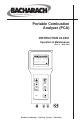
Portable Combustion Analyzer (PCA) INSTRUCTION 24-9351 Operation & Maintenance Rev. 11 – May 2004 O 2 C 2 T L q A 4 . 0 9 . 5 2 0 . 0 8 . 1 C O C U T A L A 1 2 1 5 1 9 0 1 .
PCA WARRANTY Bacharach, Inc. warrants to Buyer that at the time of delivery this Product will be free from defects in material and manufacture and will conform substantially to Bacharach Inc.’s applicable specifications. Bacharach’s liability and Buyer’s remedy under this warranty are limited to the repair or replacement, at Bacharach’s option, of this Product or parts thereof returned to Seller at the factory of manufacture and shown to Bacharach Inc.
PCA Contents Contents 1.0 INTRODUCTION ............................................................................ 1-1 1.1 The Portable Combustion Analyzer ........................................... 1-1 1.2 Displayed Data ........................................................................... 1-2 1.3 Sensor Configurations ................................................................ 1-3 2.0 TECHNICAL CHARACTERISTICS ............................................ 2-1 3.0 SETTING UP THE PCA..........
PCA Contents 4.22 4.23 4.24 4.25 Saving Test Data ................................................................... Printing Test Data ................................................................. Clear Memory Screen ............................................................ Resetting the Microprocessor ................................................ 4-28 4-29 4-31 4-31 5.0 CALIBRATION ................................................................................ 5-1 5.1 Sensor Check .......
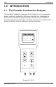
PCA Introduction 1.0 INTRODUCTION 1.1 The Portable Combustion Analyzer The Portable Combustion Analyzer (PCA) (Figure 1-1) is a commercial grade, hand held, combustion efficiency analyzer that is designed for continuous (on demand) sampling of light industrial and residential furnaces, appliances, and boilers. The basic instrument is supplied with a probe, instruction manual, batteries, and carrying case. O 2 C 2 T L q A 4 . 9 . 2 0 . 8 . 0 5 0 1 C O C U T A L A 1 2 1 5 1 9 0 1 .
PCA Introduction 1.
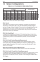
PCA Introduction 1.3 Sensor Configurations TABLE 1-1. PCA SENSOR CONFIGURATIONS PCA Models Sensors Installed Standard Advanced PCA Part No.* Part No.** PCA Part No.* Part No.** Stack Temp., CO NX Model 2424Model 2424Air Temp.
Introduction PCA PCA 35 & 65 with Draft, CO & NX These instruments are capable of measuring, displaying, and saving all measurements as previously described. Printout Capability All PCAs have the ability to print the latest test data, or any of the saved tests, to an optional printer using HP, IrDA or RS-232 protocol.
PCA Technical Characteristics 2.0 TECHNICAL CHARACTERISTICS The PCA Directly Measures and Displays: • Oxygen content in flue gas in the range of 0.1 to 20.9 % O2 • Flue gas temperature in the range of –18 to 1200 ºC (0 to 2192 ºF) • Primary-air / ambient temperature is in the range of –18 to 999 ºC (0 to 999 ºF) Optional . . . • Differential pressure/draft in the range of ±70.
PCA Technical Characteristics Normal Operating Conditions: Temperature: Analyzer ................... 0 to 40 ºC (32 to 104 ºF) Probe ......................... 800 ºC (1472 ºF) Max. Humidity: Analyzer ................... 15 to 90% Relative Humidity, Non-Condensing Air Pressure: Analyzer ................... Atmospheric Probe ......................... 25 mb (10" H2O) draft max at probe tip Performance: Accuracy: Oxygen* .................... ±0.3% O2 Carbon Monoxide .....
PCA Technical Characteristics Display: 20 character by 4 line alphanumeric LCD panel with a green backlight. Power Requirements: Four disposable AA alkaline batteries. Battery backup for the real-time clock, RAM, and bias voltage for the Nitric Oxide sensor are provided by internal lithium batteries. Optional AC Power Supplies (110 VAC & 230 VAC) are also available.
PCA Technical Characteristics Agency Approvals: _ TÜV Agency Approved (1.BImSchV - First Ordinance of the German Federal Emissions Law) Approval Number: TÜV By RgG 168 _ CE declaration of conformity Manufacturer's name: Manufacturer's address: Bacharach, Inc.
PCA Setup 3.0 SETTING UP THE PCA 3.1 Scope Before using the PCA, you MUST: • Check the batteries or plug in an optional Power Supply (Section 3.2) • Connect the probe to the analyzer (Section 3.3) • Check the analyzer’s configuration (Section 3.4) 3.2 Power 3.2.1 Checking and Replacing the Batteries A fresh set of batteries is supplied with the PCA. Install the batteries as described below. Check for a sufficient charge prior to each use. If a LOW BATTERY message is displayed, replace the batteries. 1.
PCA Setup 3.2.2 Using the Optional Power Supply If an Optional Power Supply is to be used: 1. Connect the output plug of the Optional Power Supply to the analyzer’s power supply jack (Figure 3-2). 2. Plug the Optional Power Supply into an appropriate AC wall outlet. The analyzer will now operate and function normally. 3.3 Connecting the Probe To attach the probe to the analyzer (Figure 3-2): 1.
PCA Setup Reset Button ER POW ET RES CK T-STA T-AIR GAS Room Air / Primary Air Thermocouple (Optional) Power Supply 110V/60Hz 230V/50Hz (Optional) Pressure Reference Port (Used in the Measurement of Differential Pressure) Draft Hose Flue Gas Thermocouple Flue Gas Hose Probe Tube Water Trap / Filter Assembly Flue Gas Hose Adjustable Probe Stop Probe Handle Figure 3-2.
PCA Setup 3.4 Configuring the PCA The PCA is configured at the factory for the parameters shown below, but can be changed by following the instructions in the associated sections. Function Parameters To Change, Refer to . . . Fuel Temperature Optional Draft Language Display Mode* Time Date** Printer Natural Gas ºC MB English CO & NX HR:MIN:SEC DD.MM.YY IrDA Section 4.8 Section 4.13 Section 4.14 Section 4.15 Section 4.16 Section 4.17 Section 4.17 Section 4.
Operation PCA 4.0 OPERATION 4.1 Key Pad Functions Descriptions of the key pad functions are given below. Note that most of the front panel key pad buttons perform multiple functions as determined by what screen is being displayed at the time. Turns the analyzer ON and OFF. Note that there is a 5 second delay before the instrument actually turns OFF, thus allowing an operator to turn the instrument back ON by pressing the key to prevent the accidental loss of test data.
PCA Operation 4.2 Sampling Hole Location The analyzer requires that a 13 mm (½ in.) diameter sampling hole be made in the furnace stack to accommodate the probe stop on the Probe and Hose Assembly. Locate the sampling hole downstream from the last heat exchanger, and upstream from any source of dilution, such as a draft diverter (Figure 4-1).
Operation PCA 4.3 Combustion Test IMPORTANT! Large rapid changes in the temperature of the analyzer can affect its accuracy. This is important to know if the analyzer is stored in a cold place (such as an unheated vehicle in the winter) and then taken into a warm furnace area. For the most accurate test results, allow the analyzer to warm up to room temperature before use (about 10 minutes). 4.3.
Operation PCA 4.3.2 Installing Probe in the Stack 1. After making a sampling hole in the stack (Section 4.2), and turning on the analyzer (Section 4.3.1), screw the probe stop supplied with the Probe and Hose Assembly into the sampling hole (Figure 4-2). 2. Insert the probe through the hole in the probe stop, then position the probe tip inside the stack, near its center. Tighten the thumbscrew on the probe stop to secure the probe. PROBE STOP THUMBSCREW Figure 4-2.
Operation PCA 4.3.3 Performing a Combustion Test IMPORTANT: If the burner’s primary-air temperature is not the same as the room temperature, then be sure the Optional Room Air / Primary Air Thermocouple is installed per Section 3.3. 1. With the Combustion Test Screen displayed and the probe installed in key to start a combustion test (refer to Secthe stack, press the tion 4.7). 2. Once all sensor readings are indicated on the screen: A) Loosen the thumbscrew on the probe stop.
PCA Operation CAUTION: Do not place a hot probe inside the instrument’s carrying case. Allow the probe to cool before storage. 2. Loosen the thumbscrew on the probe stop; then remove the probe and probe stop from the stack. 3. If data was saved during the combustion test, you can turn off the analyzer and review or print the stored data at a later time as described in Sections 4.10 and 4.23. 4.3.5 Turning Off the Analyzer and Purging the CO Sensor Turn off the analyzer by pressing the key.
Operation PCA 4.4 Differential Pressure Measurement The difference in pressure (∆P) between two areas can be measured by using the PCA’s two pressure ports and DRAFT Screen. By using Pressure Port 2 (–) as the reference, the pressure applied to Port 1 (+) will be displayed on the DRAFT Screen as the differential pressure between the two ports. 1.
PCA Operation 4.5 Warmup Screen BACHARACH, INC. PCA xx WARMUP yy Where: xx = Instrument Model Number yy = Counts down from 60 seconds As soon as the key is pressed, the instrument’s serial number and software version number are displayed for approximately 3 seconds. To continuously display these items, hold down the key at start-up. The warmup cycle continues after the key is released.
Operation PCA 4.6 Sensor Status Screen BACHARACH, INC. PCA xx WARMUP 0 z Where: xx = Instrument Model Number z = Sensor(s) in error If there is problem with one or more of the sensors, the Sensor Status Screen will be displayed after the analyzer has gone through its warmup cycle (refer to Section 7.2 for a listing of the error codes).
PCA Operation 4.7 Combustion Test Screen PCA models 10–25, 40–55 O2 C2 TL qA 4.0 9.5 20.0 8.1 CO CU TA LA 12 HLD 15 NG 190 P 1.24 «S This screen shows: PCA models 30, 35, 60, & 65 O2 C2 TL qA 4.0 9.5 20.0 8.1 O2 C2 TL qA 4.0 9.5 20.0 8.1 CO NX TA LA 12 HLD 10 NG 190 P 1.24 «S - OR CU 15 HLD NU 12 NG TA 190 P LA 1.24 «S O2 ............... Oxygen content in flue gas (%) C2 ............... Carbon Dioxide content present in flue gas (%) TL ............... Primary/Ambient air temp. (°F) qA ........
Operation PCA 4.8 Fuel Selection Screen «NATGAS KOKS LEG LPG FUEL OIL NO.2 OIL NO.6 P-COAL This screen is displayed by pressing the MENU key from the Combustion Test Screen. This screen is used to select the fuel being burned. To select a fuel, first use the st keys to move the cursor (z) in front of the desired fuel, and then press the key. NOTE: The fuel selected is saved as the default, and remains in memory after the PCA is turned off.
PCA Operation 4.9 Draft Screens The first Draft Screen is displayed by repeatedly pressing the MENU key from the Combustion Test Screen. To measure draft, first zero the analyzer’s pressure sensor to atmospheric pressure by disconnecting the draft hose from the bottom of the instrument, and then pressing the key. Reconnect the draft hose after the second Draft Screen appears (shown for 3 seconds). The third screen shows the current values of draft and stack temperature as measured by the analyzer.
Operation PCA 4.10 Memory Directory Screen ‘Standard’ PCA Screen MEMORY DIRECTORY «M8 28.7.97 15:45 M9 MEMORY EMPTY CLEAR MEMORY ‘Advanced’ PCA Screen MEMORY DIRECTORY «98 28.7.97 15:45 99 MEMORY EMPTY CLEAR MEMORY The Memory Directory Screen is displayed by repeatedly pressing the MENU key from the Combustion Test Screen. This screen is used to select a memory location that contains saved data which an operator can review.
PCA Operation 4.11 Memory to PC Screen (For ‘Advanced’ PCA Models 40, 45, 50, 55, 60 & 65) MEMORY TO PC «TRANSMIT DATA CLEAR MEMORY The Memory To PC Screen is displayed by repeatedly pressing the MENU key from the Combustion Test Screen. Use this screen to either transmit all stored memory locations to a computer, or clear all memory locations.
Operation PCA Data is transmitted to a computer in ASCII comma-delimited format, which can be captured as a text file and then opened in most commercially available spreadsheet programs. Note that each data record consists of 20 fields, some of which may be blank for different tests and PCA models as listed in Tables 4-1 & 4-2. Use the communication software to capture and save the received data as an ASCII text file.
PCA Operation TABLE 4-1. COMMA-DELIMITED FIELDS Field Data Name or Value 1 2 3 4 5 6 71 81 91 101 111 121 131,2 141,2 151,3 161,3 171 181 19 20 Instrument serial number ID line 1 (up to 16 characters) ID line 2 (up to 16 characters) ID line 3 (up to 16 characters) Time of test (hh:mm:ss) Date of test (dd.mm.
Operation PCA 4.12 ID Setup Screens (For ‘Advanced’ PCA Models 40, 45, 50, 55, 60 & 65) «ID #1 ID #2 ID #3 SETUP This initial ID Setup Screen is displayed by repeatedly pressing the MENU key from the Combustion Test Screen. Use this screen to edit three lines of customer information (i.e., the customer’s name, location, and burner reference number). Each ID line can be up to 16 alphanumerical characters in length.
PCA Operation Press to save the selected character and advance to the next position. If you make a mistake, press until the cursor is over the incorrect character and make your correction by again using the st keys. After all the desired characters have been selected, press the key to save the text line and return to the initial ID SETUP Screen. NOTE: The entered ID information will be saved with all future memory records until it is modified or deleted.
Operation PCA 4.13 Temperature Setup Screen SETUP TEMPERATURE UNIT «°C °F The Temperature Setup Screen is displayed by repeatedly pressing the MENU key from the Combustion Test Screen. Use this screen to setup the analyzer to display temperature in either °C or °F. To select the instrument’s temperature unit-of-measure, first use the keys to move the cursor (z) in front of °C or °F, and then press the key.
PCA Operation 4.14 Draft Unit Setup Screen DRAFT UNIT SETUP «MB PA WC The Draft Unit Setup Screen is displayed by repeatedly pressing the MENU key from the Combustion Test Screen. Use this screen to setup the analyzer to display draft in either millibars (MB), Pascals (PA), or inchesof-water column (WC). To select the draft unit-of-measure, first use the st keys to move the cursor (z) in front of MB, PA or WC, and then press the key.
Operation PCA 4.15 Language Setup Screen LANGUAGE DAN DEU «ENG SETUP NED - OR SVE FIN LANGUAGE DEU «ENG ESP SETUP FRA ITA POL The Language Setup Screen is displayed by repeatedly pressing the MENU key from the Combustion Test Screen. Use this screen to select the language displayed on the analyzer. The languages available for selection include: Danish, German, English, Dutch, Swedish and Finnish; or German, English, Spanish, French, Italian and Polish.
PCA Operation 4.16 Display Mode Setup Screen (For PCA Models 30, 35, 60 & 65) DISPLAY SETUP «CO NX CU NU The Display Setup Screen is displayed by repeatedly pressing the MENU key from the Combustion Test Screen. Use this screen to select whether the Combustion Test Screen will display the measured values of Carbon Monoxide and Nitric Oxide (CO and NX), or the calculated values of these gases (CU and NU) referenced to 0% Oxygen.
Operation PCA 4.17 Time/Date Setup Screen «TIME DATE SETUP 15:45:06 31.10.01 The Time/Date Setup Screen is displayed by repeatedly pressing the MENU key from the Combustion Test Screen. Use this screen to enter the current time and date. To enter the correct time or date, first use the st keys to move the cursor (z) in front of the function you wish to change.
PCA Operation 4.18 Printer Setup Screen «IR - HP IR - IRDA RS232 SETUP PRINTER The Printer Setup Screen is displayed by repeatedly pressing the MENU key from the Combustion Test Screen. Use this screen to choose the type of connection and printer being used.
Operation PCA 4.19 Maintenance Password Screen MAINTENANCE «PASSWORD XXX Where: xxx = Password number The Maintenance Password Screen is displayed by repeatedly pressing the MENU key from the Combustion Test Screen. From here a three-digit password must be entered to access the instrument’s Maintenance Screens. The password number is provided on the Portable Combustion Analyzer Calibration Password card that was supplied with the analyzer.
PCA Operation 4.20 Maintenance Screen MAINTENANCE «CALIBRATION USER NAME The Maintenance Screen is displayed after entering the correct password in the Maintenance Password Screen (Section 4.19). Use this screen to enter either the analyzer’s Calibration Screen or User Name Screen. To enter the Calibration Screen, first use the st keys to position the cursor (z) in front of CALIBRATION, and then press the key. NOTE: Section 5.0 contains detailed calibration procedures.
Operation PCA 4.21 User Name Screens «LINE 1 LINE 2 LINE 3 USER NAME This initial User Name Screen is displayed after selecting USER NAME from the Maintenance Screen (Section 4.20). Use this screen to either enter or edit three lines of user-name information. Each user-name line can be up to 20 alphanumerical characters in length. All three lines will appear at the top of each printout for the purpose of identifying the user or owner of the instrument (i.e., your company’s name and address).
PCA Operation Press to save the selected character and advance to the next position. If you make a mistake, press until the cursor is over the wrong character and make your correction by again using the st keys. After all the desired characters have been selected, press text line and return to the initial User Name Screen.
PCA Operation 4.23 Printing Test Data O2 C2 TL qA 4.0 9.5 20.0 8.1 CO 12 HLD CU 15 NG TA 190 «P LA 1.24 S DRAFT DRAFT – 0.25 MB HOT SPOT 190 °C «P S Before printing, ensure that the correct connection and printer has been selected per Section 4.18. The Print function is available in either the Combustion Test Screen or the Draft Screen*. NOTE: The data which is stored in memory can also be printed. First go to the Memory Directory Screen (Section 4.
PCA Operation When using a serial printer: 1. First connect the analyzer to the printer using the optional RS-232 cable (see Figure 4-6). 2. Set the printer’s communication parameters to 9600 baud, 8 data bits, 1 stop bit, no parity, and no handshaking. 3. Use the st keys to move the cursor (z) in front of the print (P) function. 4. Press the key to start printing. A t t a c h D B 9 C o n n e c t o r t o p r in t e r 's s e r ia l in p u t p o r t.
Operation PCA 4.24 Clear Memory Screen CLEAR MEMORY C «E The Clear Memory Screen is accessed from either the Memory Directory Screen (Section 4.10) or the Memory to PC Screen (Section 4.11). To clear all memory locations, use the st keys to place the cursor (z) in front of the clear (C) function, and then press the key. To return to the previous screen without clearing any memory locations, use the st keys to place the cursor (z) in front of the exit (E) function; then press . 4.
Operation PCA NOTES: 4-32 Instruction 24-9351
PCA Calibration 5.0 CALIBRATION NOTE: Bacharach recommends that the PCA be calibrated by your nearest Bacharach Service Center. Calibration, however, can be performed in the field if your facility has the necessary equipment and qualified personnel to perform the procedures described in the sections that follow. IMPORTANT! To prevent the loss of data during calibration, perform the following procedures with fresh batteries, or using an optional Power Supply (see Section 3.2). 5.
PCA Calibration 5.2 Calibration Fixtures A gas and a draft fixture will be required to perform the various calibration procedures described in this manual. Material Required: • Calibration Kit (Refer to Section 8.2) • Calibration Gas Cylinder (Refer to Section 8.2) • Bellows • Micromanometer Procedure: Assemble the appropriate fixture, shown in Figure 5-1, as required by the calibration procedure being performed. GAS FIXTURE Leave Top Port Open 2 3 4 3 5 1 M E N U 3 P C A Parts Shown: 6 1.
PCA Calibration 5.3 Calibrate Menu Screen «TA-ZERO TA-SPAN TL-ZERO TL-SPAN CALIBRATE NX CO DRAFT The Calibrate Menu Screen is displayed after entering the correct password in the Maintenance Password Screen (Section 4.19) and selecting CALIBRATION from the Maintenance Screen (Section 4.20). Use this screen to select the sensor to be calibrated. Press the st keys until the cursor (z) is in front of the desired function, and then press the key.
Calibration PCA 5.4 Calibrate TA-Zero Material Required: • Thermocouple Simulator (K-type) Range: 0 to 300°C Accuracy: ±0.3°C Procedure: 1. With the analyzer turned off, first plug the simulator's K-type connector into the T-STACK jack (Figure 3-2); then turn on the analyzer and wait for its warmup cycle to complete. 2. Enter the Calibration Menu Screen per Section 5.3; then choose TA-ZERO to zero the analyzer’s stack temperature channel. 3. Adjust the simulator to 0° C (32° F).* 4.
PCA Calibration 5.5 Calibrate TA-Span Material Required: • Thermocouple Simulator (K-type) Range: 0 to 300°C Accuracy: ±0.3°C Procedure: 1. With the analyzer turned off, first plug the simulator's K-type connector into the T-STACK jack (Figure 3-2); then turn on the analyzer and wait for its warmup cycle to complete. 2. Enter the Calibration Menu Screen per Section 5.3; then choose TA-SPAN to span the analyzer’s stack temperature channel. 3. Set the simulator to 300° C (572° F).* 4.
Calibration PCA 5.6 Calibrate TL-Zero Material Required: • Thermocouple Simulator (K-type) Range: 0 to 300°C Accuracy: ±0.3°C Procedure: 1. With the analyzer turned off, first plug the simulator’s K-type connector into the T-AIR jack (Figure 3-2); then turn on the analyzer and wait for its warmup cycle to complete. 2. Enter the Calibration Menu Screen per Section 5.3; then choose TL-ZERO to zero the analyzer’s room-air/primary-air temperature channel. 3. Set the simulator to 0 °C (32 °F).* 4.
PCA Calibration 5.7 Calibrate TL-Span Material Required: • Thermocouple Simulator (K-type) Range: 0 to 300°C Accuracy: ±0.3°C Procedure: 1. With the analyzer turned off, first plug the simulator’s K-type connector into the T-AIR jack (Figure 3-2); then turn on the analyzer and wait for its warmup cycle to complete. 2. Enter the Calibration Menu Screen per Section 5.3; then choose TL-SPAN to span the analyzer’s room-air/primary-air temperature channel. 3. Set the simulator to 100 °C (212 °F).* 4.
Calibration PCA 5.8 Calibrate NX (For PCA Models 30, 35, 60 & 65) The Nitric Oxide sensor needs to be spanned at regular intervals to determine that it still meets its accuracy specification. Because of the toxicity of Nitric Oxide gas, however, unless your facility has the necessary gas cylinders and personnel trained in the handling of toxic gases, we recommend that the Nitric Oxide sensor be spanned by an authorized Bacharach Service Center. Material Required: • Calibration Gas Fixture (Section 5.
PCA Calibration 5.9 Calibrate CO (For PCA Models 20, 25, 30, 35, 50, 55, 60 & 65) Material Required: • Calibration Gas Fixture (Section 5.2) • Gas Cylinder, 500 ppm CO in air (Refer to Section 8.2) • Gas Cylinder, CO (1000 ppm) and H2 (1000 ppm) in Nitrogen (Refer to Section 8.2) Procedure: 1. Enter the Calibrate Menu Screen per Section 5.3. Then choose to calibrate the CO sensor. 2. At the conclusion of Step 1 the pump should start running. 3.
Calibration PCA 7. Turn off the flow of CO calibration-gas; then remove the calibrationgas cylinder from the calibration fixture. 8. Attach a CO/H2 calibration-gas cylinder to the calibration fixture; then adjust the regulator of the calibration fixture for a flowmeter reading of approximately 2 SCFH. keys to enter a CO-VALUE that is the same as 9. Use the st and the CO concentration which is stamped on the CO/H2 calibration-gas cylinder.
Calibration PCA 5.10 Calibrate Draft (For PCA Models 15, 25, 35, 45, 55 & 65) Material Required: • Calibration Fixture (Section 5-2) • Bellows (adjustable) • Micromanometer Range: ±20 mb (±8 in. H2O column) Accuracy: ±0.025 mb (±0.01 in. H2O column) Procedure: IMPORTANT! In Step 1, do not connect the draft calibration fixture to the analyzer until the Calibrate Draft Screen has been selected and displayed. 1. Enter the Calibrate Menu Screen per Section 5.3. Then choose to calibrate the draft sensor. 2.
Calibration PCA NOTES: 5-12 Instruction 24-9351
PCA Maintenance 6.0 MAINTENANCE 6.1 Routine Maintenance Routine maintenance of the analyzer consists of: replacing the batteries, cleaning the probe, draining the water trap, replacing the water trap filter, and performing periodic calibration checks to ensure that the analyzer is providing accurate readings. • Replace the Batteries per Section 3.2. • Clean the Probe per Section 6.3. • Maintain the Water Trap/Filter Assembly per Section 6.4. • Replace the Particulate Filter per Section 6.
PCA Maintenance 6.2 Disassembly Perform the following when a maintenance procedure calls for removing the case, printed circuit board, pump, or sensors: 1. Remove the batteries (Section 3.2.1) 2. Place the analyzer face down on a work surface, then remove the unit’s four rear-case screws. 3. Carefully lift the rear case from the analyzer, unplug the battery compartment wires, then place the rear housing on a work surface (see Figures 6-1 & 6-2). B A T T E R Y W IR E S Figure 6-1.
PCA Maintenance BIAS BATTERY CO PCB TO BATTERY COMPARTMENT FUSE NX PCB OPTIONAL CARBON MONOXIDE SENSOR OPTIONAL NITRIC OXIDE SENSOR PUMP MTG. SCREWS OXYGEN SENSOR – PUMP + RED BLACK 4 PARTICULATE FILTER DRAFT SENSOR Figure 6-2.
Maintenance PCA 6.3 Cleaning the Probe The Probe Tube and the Probe Body will become dirty under normal use (the water trap’s filter element should prevent soot from reaching the analyzer’s internal components). If the probe assembly is not kept clean, it could become clogged and restrict the flow of gas to the analyzer, resulting in incorrect readings and calculations.
PCA Maintenance 6.4 Water Trap/Filter Assembly Maintenance The Water Trap / Filter Assembly removes water condensate from the gas sample, and also prevents soot from contaminating the internal components of the analyzer. Drain the water condensate after every use. Procedure: 1. Pull off the end-cap from the Inlet End of the Water Trap / Filter Assembly (Figure 6-3). 2. Pour out all of the water condensate, and replace the end-cap. Replace the filter element when it becomes excessively dirty.
Maintenance PCA 6.5 Replacing the Particulate Filter The internal particulate filter (Figure 6-2) prevents small dust and dirt particles from entering and damaging the pump. Depending on your environmental conditions, it is recommended to change the particulate filter and fitting approximately every six months, or sooner if it becomes blocked. Equipment Required: • Particulate Filter and Fitting (Refer to Section 8.0) Procedure: 1. Remove the analyzer’s rear case and lay it aside (refer to Section 6.2).
Maintenance PCA 6.6 Replacing the Oxygen Sensor Replace the Oxygen Sensor when it has expired (when the analyzer’s automatic O2 calibration fails and the unit displays the message “O2Sensor Error”). NOTE: A "O2-SENSOR ERROR" displayed in the Sensor Status Screen does not necessarily mean that the sensor has expired. Before replacing the sensor, refer to Section 7.2 for other possible causes of the error. Equipment Required: • Small Flat Blade Screw Driver • Oxygen Sensor (Refer to Section 8.
Maintenance PCA 6.7 Replacing the Nitric Oxide Sensor (For PCA Models 30, 35, 60 & 65) Replace the Nitric Oxide sensor when it has expired (can no longer be calibrated). NOTE: A "NX-SENSOR ERROR" displayed in the Sensor Status Screen does not necessarily mean that the sensor has expired. Before replacing the sensor, refer to Section 7.2 for other possible causes of the error. Equipment Required: • Small Flat Blade Screw Driver • Nitric Oxide Sensor (Refer to Section 8.
Maintenance PCA 6.7.2 Replacing the Nitric Oxide Sensor Bias Battery A single lithium battery, located on the Nitric Oxide printed circuit board (see Figure 6-2), applies a constant bias voltage to the Nitric Oxide sensor even while the instrument is turned off. This battery has a life expectancy of at least 2 years. Replace the Nitric Oxide bias battery toward the end of its expected life. Equipment Required: • Bias Battery (See Section 8.0) Procedure: 1.
PCA Maintenance 6.8 Replacing the Carbon Monoxide Sensor (For PCA Models 20, 25, 30, 35, 50, 55, 60 & 65) Replace the Carbon Monoxide sensor when it has expired (can no longer be calibrated). NOTE: A "CO-SENSOR ERROR" displayed in the Sensor Status Screen does not necessarily mean that the sensor has expired. Before replacing the sensor, refer to Section 7.2 for other possible causes of the error. Equipment Required: • Small Flat Blade Screw Driver • Carbon Monoxide Sensor (Refer to Section 8.
PCA Maintenance 6.8.1 Replacing the Carbon Monoxide Sensor Filter Replacing the red filter on the Carbon Monoxide sensor once a year could increase the life of the sensor. Procedure: 1. Remove the Carbon Monoxide sensor per Section 6.8. 2. Pry the red filter from the Carbon Monoxide sensor and replace it with a new one. 3. Reinstall the sensor.
Maintenance PCA 6.9 Replacing the Pump Assembly Replace the Pump Assembly if it is found to be defective. Equipment Required: • Small Flat Blade Screw Driver • No. 1 Phillips Screw Driver • Pump Assembly (Refer to Section 8.0) Procedure: 1. Remove the analyzer’s rear case and lay it aside (refer to Section 6.2). 2. Remove the two self tapping Phillips screws holding the Pump Assembly (See Figure 6-1). 3.
PCA Troubleshooting 7.0 TROUBLESHOOTING 7.1 Analyzer Repair It is recommended that field repair of the PCA be limited to: • Simple checks of the printed circuit boards • Replacing the Probe Assembly • Replacing the filter element in the Water Trap / Filter Assembly • Replacing the Particulate Filter • Replacing the Pump Assembly • Replacing Sensors and Sensor Filters • Replacing Batteries All other repairs should be performed by an authorized Bacharach Service Center.
PCA Troubleshooting 7.2 Error Codes If one of the following messages appear at the bottom of the Sensor Status Screen, refer to Section 7.3 Troubleshooting Guide for information on how to correct the error. O2 - SENSOR ERROR O2 Sensor not connected, or is expired, or was exposed to combustion gases during warmup. CO - SENSOR ERROR Carbon Monoxide sensor is expired, or was exposed to Carbon Monoxide during warmup.
PCA Troubleshooting 7.3 Troubleshooting Guide The following table lists the causes and remedies for most of the problems that may arise with the analyzer. For help with any problem not discussed here, contact your nearest Bacharach Service Center. TABLE 7-1. TROUBLESHOOTING GUIDE Fault Probable Cause & Remedy Analyzer completely nonfunctional; won’t turn on when the key is pressed. a. Batteries dead. Replace batteries per Section 3.2. b. Loose battery connector.
Troubleshooting PCA TABLE 7-1. TROUBLESHOOTING GUIDE (Cont.) Fault Probable Cause & Remedy NX-SENSOR ERROR code appears in the Sensor Status Screen. a. Calibration was attempted while sampling combustion gases. b. Nitric Oxide sensor is expired. Replace sensor per Section 6.7. c. Bias battery on the Nitric Oxide circuit board is dead. Replace battery per Section 6.7.2. CO-SENSOR ERROR code appears in the Sensor Status Screen. a. Calibration was attempted while sampling combustion gases. b.
PCA Troubleshooting TABLE 7-1. TROUBLESHOOTING GUIDE (Cont.) Fault Probable Cause & Remedy “- - - -” appears in one or more value a. The analyzer is not able to calcufields of the Combustion Test Screen. late a numerical value based on measured combustion data. The “- - - -” is replaced with numerical values when the analyzer begins to detect valid combustion data. b. Sensor in error during warm-up. “XXXX” appears in one or more value The field’s associated sensor is defields.
PCA Troubleshooting TABLE 7-1. TROUBLESHOOTING GUIDE (Cont.) Fault Probable Cause & Remedy Backlight won’t turn on. Backlight LED burned out. Return to Bacharach for repair. Batteries do not last 10 hours. Cold temperature is reducing battery capacity. To obtain longer operating time, keep analyzer warm. Erratic Combustion Test Screen a. Faulty sensor(s): values. - Check that the sensors are properly installed per Sections 6.6 through 6.8. - Check sensor calibration per Section 5.0.
PCA Parts & Service 8.0 PARTS & SERVICE 8.1 Replacement Parts Item Figures 8-1, 2 & 3 1 2 3 Description Part No.
PCA Parts & Service 8.2 Accessories Description Part No. STANDARD ACCESSORIES: Battery, “AA” Alkaline Complete Probe and Hose Assembly (Gas & Draft) Instruction Manual Plastic Carrying Case 204-0004 24-3004 24-9351 24-1078 OPTIONAL ACCESSORIES: Ambient Thermocouple, 10 ft. K-type Ambient Thermocouple, 1 in.
PCA Parts & Service 2 1 3 Figure 8-1.
PCA Parts & Service FUSE 14 15 9 10 11 12 8 – + 13 RED BLACK 4 23 24 22 21 Figure 8-2.
PCA Parts & Service 2 0 1 9 1 8 2 5 Figure 8-3.
PCA Parts & Service 8.3 Sales/Service Centers Replacement parts and service can be obtained by contacting one of the following Bacharach Sales/Service Centers: UnitedStates California 7281 Garden Grove Blvd., Suite H Garden Grove, CA 92841 Phone: 714-895-0050 Fax: 714-895-7950 Email: calservice@bacharach-inc.com Ind iana Indiana 8618 Louisiana Place Merrillville, IN 46410 Phone: 219-736-6178 Fax: 219-736-6269 Email: indservice@bacharach-inc.com New Jersey 7300 Industrial Park Rte. 130, Bldg.
PCA Appendix A APPENDIX A Display Screen Translations This appendix shows the contents of the various screen displays that are seen while operating the PCA in all ten languages that the analyzer is capable of displaying. The language that is displayed on the analyzer is dependent on the analyzer’s model (refer to Table 1-1), and the language selected per Section 4.15. The languages are arranged in columns side-by-side for comparison and translation purposes.
Appendix A English (ENG) PCA German (DEU) Danish (DAN) French (FRA) Spanish (ESP) Warm Up Screen BACHARACH, INC. BACHARACH, INC. BACHARACH, INC. BACHARACH, INC. BACHARACH, INC.
PCA Polish (POL) Appendix A Italian (ITA) Dutch (NED) Swedish (SVE) Finnish (FIN) BACHARACH, INC. BACHARACH, INC. BACHARACH, INC. BACHARACH, INC. BACHARACH, INC.
Appendix A English (ENG) PCA German (DEU) Danish (DAN) French (FRA) Spanish (ESP) Saving Memory Screen SAVING MEMORY Speichere Daten in LAGRING MEMORY SAUVEGARDE D MEMOIRE GUARDANDO UBIBACION LOCATION nn Block nn BLOK nn ZONE nn DE MEMORIA nn DIRECTORIO MEMORI Memory Directory Screen MEMORY DIRECTORY SPEICHER LISTE MEMORY BIBLIOTEK REPERTOIRE MEMRE MEMORY EMPTY Speicher leer MEMORY TOM MEMOIRE VIDE MEMORIA VACIA CLEAR MEMORY Speicher Lˆschen SLET MEMORY EFFACER MEMOIRE BORRAR M
Appendix A PCA Polish (POL) Italian (ITA) Dutch (NED) Swedish (SVE) Finnish (FIN) ZACHOWYWANIE MIEJSCE SALVARE MEMORIA OPSLAAN IN GEHEUGEN Sparar minne TALLENTAA MUISTI W PAMIECI nn UBICAZIONE nn LOCATIE nn i block nn PAIKKAAN nn KATALOG PAMIECI INDIRIZZ MEMORIA INHOUD GEHEUGEN MINNES BIBLIOTEK MUISTITIEDOSTO PAMIEC PUSTA MEMORIA VUOTA GEHEUGEN LEEG Minnet tomt MUISTI TYHJfl WYCZYSC PAMIEC ANNULARE MEMORIA GEHEUGEN WISSEN Rensa minnet TYHJENNfl MUISTI CIAG MEM TIRAGGIO MEM
Appendix A English (ENG) PCA German (DEU) Danish (DAN) French (FRA) Spanish (ESP) Time/Date Setup Screen SETUP KONFIGURIEREN OPSAETNING PROGRAMMER ESTABLECER TIME Zeit TID HEURE HORA DATE Datum DATO DATE FECHA Maintenance Password Screen MAINTENANCE INSTANDHALTUNG VEDLIGEHOLDELSE MAINTENANCE MANTENIMIENTO PASSWORD Kennwort KODEORD MOT DE PASSE CONTRASENA Printer Setup Screen SETUP PRINTER KONFIGURIEREN PRINTER OPSAETNING PRINTER PROGRAMMER PRINTER ESTABLECER PRINTER IR-HP
Appendix A PCA Polish (POL) Italian (ITA) Dutch (NED) Swedish (SVE) Finnish (FIN) USTAW PREPARAZIONE INSTELLINGEN KONFIG ASETUKSET CZAS ORA TIJD Tid AIKA DATE DATA DATUM Datum PƒIVƒ UTRZYMANIE MANTENIMENTO ONDERHOUD UNDERHALL YLLƒPITO HASTO PAROLA DORDINE PASWOORD PASSWORD SALASANA USTAW PRINTER PREPARAZIONE PRINTER INSTELLINGEN PRINTER KONFIG PRINTER ASETUKSET PRINTER IR-HP/IR-IRDA/RS232 IR-HP/IR-IRDA/RS232 IR-HP/IR-IRDA/RS232 IR-HP/IR-IRDA/RS232 IR-HP/IR-IRDA/RS232
Appendix A English (ENG) PCA German (DEU) Danish (DAN) French (FRA) Spanish (ESP) KALIBRER CALIBRER CALIBRAR Calibrate TL-Span Screen CALIBRATE TL-SPAN ABGLEICHEN TL-GAIN TL-SPAN FRCHETTE-TL TL-TRAM MEASURED Ist-Wert MAALT MESURE MEDIDA APPLIED Soll-Wert SAND VAERDI APPLIQUE APLICADA CALIBRAR NX Calibrate NX Screen CALIBRATE NX ABGLEICHEN NX-GAIN KALIBRER NX CALIBRER NX MEASURED Ist-Wert MAALT MESURE MEDIDO APPLIED Soll-Wert SAND VAERDI APPLIQUE APLICADO CALIBRAR CO
Appendix A PCA Polish (POL) Italian (ITA) Dutch (NED) WZORCUJ CALIBRARE IJKING TL-ROZPIETOS TL-DIFF T-OMG-1 Swedish (SVE) CALIBRATE TL-SPAN Finnish (FIN) KALIBROI TI-YLflRAJA MIERZONA MISURATO GEMETEN MEASURED MITATTU STOSOWANA APPLICATO AANGELEGD APPLIED SY÷TETTY WZORCUJ NX CALIBRARE NX IJKING NX-METING CALIBRATE NX KALIBROI NX MIERZONE MISURATO GEMETEN MEASURED MITATTU STOSOWANE APPLICATO AANGELEGD APPLIED SY÷TETTY WZORCUJ CO CALIBRARE CO IJKING CO-METING CALIBRATE
Appendix A PCA NOTES: A-10 Instruction 24-9351
Appendix B PCA APPENDIX B – Printout Translations English (ENG) German (DEU) Danish (DAN) Combustion Test Data [Line 1: user name] [Line 2: user name] [Line 3: user name] [Line 1: user name] [Line 2: user name] [Line 3: user name] [Line 1: user name] [Line 2: user name] [Line 3: user name] BACHARACH, INC. PCA 65 SN: xxxxxx ==================== BACHARACH, INC. PCA 65 SN: xxxxxx ==================== BACHARACH, INC.
PCA Appendix B French (FRA) Spanish (ESP) Polish (POL) Combustion Test Data [Line 1: user name] [Line 2: user name] [Line 3: user name] [Line 1: user name] [Line 2: user name] [Line 3: user name] [Line 1: user name] [Line 2: user name] [Line 3: user name] BACHARACH, INC. PCA 65 SN: xxxxxx ==================== BACHARACH, INC. PCA 65 SN: xxxxxx ==================== BACHARACH, INC.
Appendix B PCA Italian (ITA) Dutch (NED) Swedish (SVE) Combustion Test Data [Line 1: user name] [Line 2: user name] [Line 3: user name] [Line 1: user name] [Line 2: user name] [Line 3: user name] [Line 1: user name] [Line 2: user name] [Line 3: user name] BACHARACH, INC. PCA 65 SN: xxxxxx ==================== BACHARACH, INC. PCA 65 SN: xxxxxx ==================== BACHARACH, INC.
Appendix B PCA Finnish (FIN) Combustion Test Data [Line 1: user name] [Line 2: user name] [Line 3: user name] BACHARACH, INC. PCA 65 SN: xxxxxx ==================== [ID1: [ID2: [ID3: optional optional optional AIKA PÄIVÄ data] data] data] 09:03:27 28.08.1998 POLTTOAI MAAKAASU SKA LäMPöT YMP LäMPöT O2 CO2 CO CO HAPETON NX NX HAPETON SAVUPIIPHä ILMäYLIMää PAINE 190 20.0 4.0 9.5 12 15 10 12 8.1 1.24 °C °C % % ppm ppm ppm ppm % -0.
PCA Instruction 24-9351
World Headquarters 621 Hunt Valley Circle, New Kensington, PA 15068 Ph: 724-334-5000 • Fax: 724-334-5001 • Toll Free: 1-800-736-4666 Website: www.bacharach-inc.com • E-mail: help@bacharach-inc.com Printed in U.S.A.