Portable Combustion Analyzer Instruction 24-9448 Operation & Maintenance Rev.
WARRANTY Bacharach, Inc. warrants to Buyer that at the time of delivery this Product will be free from defects in material and manufacture and will conform substantially to Bacharach Inc.’s applicable specifications. Bacharach’s liability and Buyer’s remedy under this warranty are limited to the repair or replacement, at Bacharach’s option, of this Product or parts thereof returned to Seller at the factory of manufacture and shown to Bacharach Inc.
Contents Contents 1 Introduction. . . . . . . . . . . . . . . . . . . . . . . . . . . . . . . . . . . 1-1 1.1 1.2 1.3 1.4 1.5 PCA 2 General Description. . . . . . . . . . . . . . . . . . . . . . . . . . . . . . . 1-1 Sales Combo & Model Configurations. . . . . . . . . . . . . . . . . . . . . . 1-2 Features & Benefits . . . . . . . . . . . . . . . . . . . . . . . . . . . . . . . . . . . . 1-4 Operational Overview. . . . . . . . . . . . . . . . . . . . . . . . . . . . . . .
Contents 4 Operation. . . . . . . . . . . . . . . . . . . . . . . . . . . . . . . . . . . . . 4-1 4.1 Operating Tips. . . . . . . . . . . . . . . . . . . . . . . . . . . . . . . . . . . . . . . . . 4-1 4.2 Turning ON the Analyzer and Warm Up . . . . . . . . . . . . . . . . . . . 4-2 4.3 Selecting a Fuel. . . . . . . . . . . . . . . . . . . . . . . . . . . . . . . . . . . . . . . . 4-3 4.4 Sampling Point . . . . . . . . . . . . . . . . . . . . . . . . . . . . . . . . . .
Contents 6 Maintenance. . . . . . . . . . . . . . . . . . . . . . . . . . . . . . . . . . . 6-1 6.1 PCA 2 Disassembly. . . . . . . . . . . . . . . . . . . . . . . . . . . . . . . . . . . . . 6-2 6.2 Water Trap / Filter Maintenance. . . . . . . . . . . . . . . . . . . . . . . . . . 6-6 6.2.1 Emptying the Water Trap Chamber . . . . . . . . . . . . . . . . . . 6-6 6.2.2 Replacing the Filter Element. . . . . . . . . . . . . . . . . . . . . . . . 6-6 6.
Contents Notes: iv Instruction 24-9448
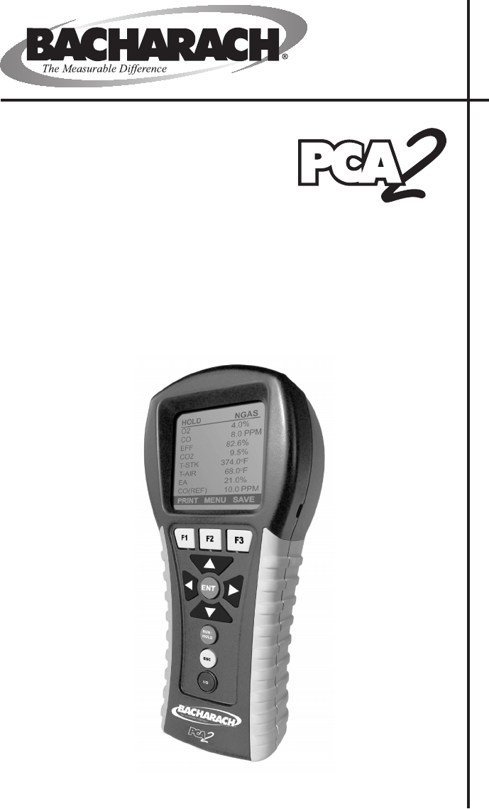
Introduction 1 Introduction 1.1 PCA 2 General Description The PCA 2 is a commercial-grade hand-held combustion and emissions analyzer designed for on-demand sampling of light industrial, institutional, commercial and residential furnaces, appliances, and boilers. The basic instrument is supplied with a probe and hose assembly, instruction manual, factory calibrated smart sensors, 4 'AA' alkaline batteries, Data Download Software with USB cable and carrying case.
Introduction 1.
Introduction Sales Combo 24-8353 24-8354 24-8355 Sales Combo (Kit) 24-8373 24-8374 24-8375 Model Type 255 265 275 24-7304 24-7305 24-7306 3 3 3 Stack Temperature 3 3 3 Primary / Ambient Air Temperature 3 3 3 Carbon Monoxide Low (COLow) 3 3 3 Pressure / Draft 3 3 3 Nitric Oxide (NO) 3 3 Nitrogen Dioxide (NO2) 3 PCA2 Only Part Number Oxygen (O2) Measurements Carbon Monoxide High (COHigh) Sulfur Dioxide (SO2) Combustion Efficiency 3 3 Calculations 3 3 3 Excess A
Introduction 1.3 Features & Benefits • Powered by 4 ‘AA’ alkaline batteries, or NiMH rechargeable batteries. An optional AC power adapter provides continuous operation. • Internal charging circuit allows rechargeable batteries to be charged inside the analyzer with the use of the optional AC power adapter. • O2 and COLow measurement standard. Optional measurement of up to two additional gases: COHigh, NO, NO2, or SO2.
Introduction •Language options including English, French, and Spanish •Custom Display Formats •Calibration Reminders - PCA2 can be set up to remind the user that calibration is past due. 1.4 Operational Overview The PCA 2 is powered by either its 4 internal batteries, or by an optional AC power adapter that operates from any convenient source of 100– 240 VAC, 50/60 Hz power. The type of batteries used can be either disposable alkaline or rechargeable NiMH.
Introduction analyzer and is placed in the burner’s primary-air stream. Begin the combustion test by first inserting the analyzer’s probe tube into the stack-gas stream of the appliance under test, and then pressing the RUN/HOLD button to display the Combustion Test RUN screen. The analyzer will begin to continuously monitor the stack temperature, %O2 and emission levels in the stack gas and then display measured and calculated values on its LCD. Values are listed in Section 2 Specifications.
Introduction IrDA – Wireless printer communications port LCD – 160 x 160 graphic display ENT: F1 / F2 / F3 – Soft Menu Buttons, whose functions are defined by labels appearing above them on LCD • Selects a highlighted menu item, or confirms the entry of data USB – Computer communications connector RUN / HOLD: • Starts and stops a combustion efficiency test Arrow Buttons: • Pressing this button during the 5 second turn-off period will keep the analyzer turned ON – Moves cursor up the display, or inc
Introduction 1.5.2 T-AIR (Primary Air Thermocouple) If thermocouple P/N 104-1797 (10 feet long) or Utility Wand P/N 104-1799 (12 inch ridged probe with handle and 5 foot coiled cable) is to be used to measure the burner’s primary air temperature, then connect either of these thermocouples to the analyzer’s T-AIR connector. 1.5.3 POWER (AC Adapter) The AC power adapter P/N 24-1404 can be used as an external power supply, which will run the analyzer on a continuous basis.
Introduction compatible IrDA wireless printer by aligning their IrDA communication ports. Refer to Section 4.16. 1.5.7 OPT (Option) The option connector is used for optional external measurement features. 1.6 Front Panel Buttons Descriptions of the front panel buttons are given below. Note that a control may perform multiple functions as determined by what screen is being displayed at the time. The functions of these buttons are defined by labels appearing above them on the LCD.
Introduction The arrow buttons move the cursor on the LCD in the direction of the arrow. In screens that require the entry of alphanumerical data, use the buttons to move cursor across the screen and then use the buttons to increment and decrement the data. When viewing a menu, use the buttons to quickly move to the top and bottom of the menu. Selects a highlighted menu. In addition, if changes were made to one of the analyzer’s operating parameters (e.g., date, time, O2 reference, etc.
Specifications 2 Specifications The PCA 2 Directly Measures and Displays: The gases displayed depend on the analyzer’s model number. Refer to Section 1.2. Oxygen . . . . . . . . . . . . . . . . . . . . . . . . . . . . . . . . . . . . . . . . . . . . . . . 0 to 20.9% Stack Temperature. . . . . . . . . . . . . . . . . . . . . –4 to 2,192 ºF (–20 to 1,200 ºC) Primary / Ambient Air Temperature . . . . . . . . . –4 to 999 ºF (–20 to 537 ºC) Carbon Monoxide (CO) (H2 compensated). . . . . . . . . . . . . . . .
Specifications Normal Operating Conditions: Temperature: Analyzer . . . . . . . . . . . . . . . . . . . . . . . . . . . . . . . . 32 to 104 ºF (0 to 40 ºC) Probe Tip. . . . . . . . . . . . . . . . . . . . . . . . . . . . . . . . . 1,472 ºF (800 ºC) Max. Humidity: Analyzer . . . . . . . . . . . . . . 15 to 90% Relative Humidity, non-condensing Air Pressure: Analyzer . . . . . . . . . . . . . . . . . . . . . . . . . . . . . . . . . . . . . . . . . Atmospheric Probe. . . . . . . . . . . . . . . . . . . . . .
Specifications Power Requirements: Four disposable ‘AA’ alkaline batteries provide at least 15 hours of continuous operation. NiMH rechargeable batteries can also be used, with the operating time dependent on battery type and condition. An optional AC power adapter, which runs from any convenient source of 100–240 VAC, 50/60 Hz power, can be used to power the analyzer on a continuous basis.
Specifications Notes: 2-4 Instruction 24-9448
Initial Setup 3 Initial Setup 3.1 Scope Before using the PCA 2, you MUST: • Install batteries, or plug in the optional AC power adapter (Section 3.2) • Connect the probe and hose assembly (Section 3.3) • Check, and if necessary, make changes to the analyzer’s configuration (Section 3.4) 3.2 Power 3.2.1 Installing or Replacing Batteries Either alkaline or NiMH rechargeable batteries can used to power the analyzer.
Initial Setup 3.2.2 Using the AC Power Adapter The AC power adapter is capable of powering the analyzer on a continuous basis. The adapter plugs into an appropriate 100–240 VAC, 50/60 Hz wall outlet, and produces an output of +9 VDC. The adapter’s output connector plugs into the analyzer’s POWER jack located on the bottom of the unit (Figure 3-2). If NiMH rechargeable batteries are used, the adapter can also rapid charge these batteries in approximately 2 - 3 hours while still inside the analyzer.
Initial Setup Option Connector (Optional External Measurement) POWER AC Power Adapter Jack (POWER) T-STACK Primary / Ambient Air Thermocouple (T-AIR) (Optional) T-AIR GAS P Differential Pressure Hose (— ∆P) (Optional) Stack Gas Thermocouple Connector (T-STACK) Draft Hose (+ ∆P) Gas Sample Hose (GAS) Probe Tube Probe Stop Water Trap / Filter Assembly Probe Handle Figure 3-2.
Initial Setup 3.4 Operating Parameters The PCA 2 is set up at the factory for the following operating parameters: Fuel. . . . . . . . . . . . . . . . . . . . . Natural Gas Temperature Units. . . . . . . . . °F Pressure Units. . . . . . . . . . . . Inches of Water Column (inwc) Pollution Units. . . . . . . . . . . . ppm Date. . . . . . . . . . . . . . . . . . . . . Current MM/DD/YY Time . . . . . . . . . . . . . . . . . . . . Current EST HH:MM AM/PM O2 Reference. . . . . . . . . . . . . . 0% Print Pressure.
Initial Setup that the name of the selected fuel should now appear at the top of the screen. Note: In addition to the standard fuels programmed into the PCA2, Bacharach can develop custom fuel codes based on the customers specific needs. The PCA2 can be programmed with 2 additional fuels which can be added to the instrument using the PC based software provided. Consult factory for price and delivery. 3.6 Temperature Units Selection Select to display temperature in either °F or °C as follows: 1.
Initial Setup 3.7 Pressure Units Selection Select to display pressure in Inches of Water Column (inwc), millibar (mb), Pascals (Pa), or hectoPascals (hPa) as follows: MAIN MENU 1. Display the MAIN MENU by pressing the MENU (F2) button. If necessary, press ESC until MENU appears above F2. FUEL PRESSURE TEMPERATURE MEMORY SETUP 2. Use the buttons to highlight SETUP, and then press ENT to display the SETUP MENU. 3.
Initial Setup 3.8 Pollution Units Selection The PCA 2 is capable of converting the measured ppm levels of CO, NO, NO2, and SO2 to various pollution units using CFR40 Part 60 emission factors. Note that the pollution-unit conversions for NO, NO2 and NOx are based on the molecular weight of NO2.
Initial Setup 3.9 Date Setup The date is stored in the format: MM/DD/YY. Its value is part of the date and time stamp that is saved along with each combustion test record. Set the analyzer’s internal clock to the current date as follows: 1. Display the MAIN MENU by pressing the MENU (F2) button. If necessary, press ESC until MENU appears above F2. 2. Use the buttons to highlight SETUP, and then press ENT to display the SETUP MENU. 3.
Initial Setup 3.10 Time Setup The time is stored in the format: hh:mm:ss AM/ PM. Its value is part of the date and time stamp that is saved along with each combustion test record. Set the analyzer’s internal clock to the current time as follows: 1. Display the MAIN MENU by pressing the MENU (F2) button. If necessary, press ESC until MENU appears above F2. 2. Use the buttons to highlight SETUP, and then press ENT to display the SETUP MENU. 3.
Initial Setup 3.11 O2 Reference Setup The measured values of CO, NOx, and SO2 can be individually referenced to a specific O2 percentage of between 0 and 15%. Individually set up the O2 reference value for each of the above gases as follows: 1. Display the MAIN MENU by pressing the MENU (F2) button. If necessary, press ESC until MENU appears above F2. 2. Use the buttons to highlight SETUP, and then press ENT to display the SETUP MENU. 3.
Initial Setup 3.12 Print Pressure Selection Select whether to print or not print the pressure measurement on the combustion test printout as follows: 1. Display the MAIN MENU by pressing the MENU (F2) button. If necessary, press ESC until MENU appears above F2. 2. Use the buttons to highlight SETUP, and then press ENT to display the SETUP MENU. 3. Use the buttons to highlight PRINT PRESSURE, and then press ENT to display the PRINT PRESSURE screen. 4.
Initial Setup 3.13 Zoom-Display Selection Combustion test data in the Run/Hold screen can be shown with enlarged characters to make viewing easier. The operator can set zoom levels to Standard, 2X, or 3X. The Standard zoom setting will display 8 lines of combustion test data at one time, 2X which will display 4 lines of combustion test data with enlarged characters, and 3X which will display 3 lines of combustion test data with enlarged characters.
Initial Setup 3.14 Battery Charger Selection When using rechargeable NiMH batteries, the AC power adapter can be used to charge the batteries while inside the analyzer. The analyzer’s rapidcharger circuit, however, must be first turned ON. IMPORTANT: When using disposable alkaline batteries, the analyzer’s battery charger circuit should be OFF to prevent the batteries from overheating.
Initial Setup 3.15 Logging Selection– When the logging function is activated, up to 500 combustion test records will be automatically stored in memory at a preset interval over a predetermined length of time. Refer to Section 4.14 for detailed information on how to select the logging function; how to set the interval and duration time periods; and how to view or download the stored data.
Initial Setup 3.17 Test ID Information Test records can be identified (e.g. customer's name, burner number, and location) by manually entering up to three lines of text, with each line containing a maximum of 20 alphanumeric characters. When a Test ID is selected this information will be associated with all succeeding test records, and will appear at the top of each test record when printed, and in Excel files when records are downloaded to a PC.
Initial Setup end this procedure by highlighting Edit Complete and pressing the ENT key to return to the Edit Test ID Menu. 9. Press ESC to go to the Test ID Menu or the RUN/HOLD key to return to the Run/Hold screen. Select a Test ID: 1. From the Test ID menu, use the buttons to highlight SELECT TEST ID, and then press ENT to display the SELECT TEST ID menu, which displays the first line of each Test ID record. 2.
Initial Setup 3.18 Username The name of the user or owner of the analyzer (e.g. company name, address, phone number) can be stored in memory by manually entering up to three lines of text, with each line containing up to 20 alphanumeric characters. This information will appear at the top of each printout, until such time as new information is entered or cleared. MAIN MENU Username Information can be entered as follows: 1. Display the MAIN MENU by pressing the MENU (F2) button.
Initial Setup To Clear a Username proceed as follows: 1. Display the MAIN MENU by pressing the MENU (F2) button. If necessary, press ESC until MENU appears above F2 MAIN MENU FUEL PRESSURE TEMPERATURE MEMORY . 2. Use the buttons to highlight SETUP, and then press ENT to display the SETUP MENU. 3. Use the buttons to highlight USERNAME, and then press ENT to display all three lines of the EDIT USERNAME screen. Periods(.....) identify empty lines. 4.
Initial Setup 3.19 Language Information on the display screen can be shown in English, French, or Spanish. Select the desired language as follows: 1. Display the MAIN MENU by pressing the MENU (F2) button. If necessary, press ESC until MENU appears above F2 MAIN MENU FUEL PRESSURE TEMPERATURE . 2. Use the buttons to highlight SETUP, and then press ENT to display the SETUP MENU. 3. Use the buttons to highlight LANGUAGE SELECTION, and then press ENT to display The Language Selection Menu. 4.
Initial Setup 3.20 Cal Reminder Period The analyzer can be set to indicate a calibration reminder during the 60 second warm-up period. Calibration reminders can be preset to occur 6, 8, 10, 12, or 15 months after the last calibration. When the preset period is exceeded the instrument will display the reminder, and how long since the sensors were last calibrated. The reminder will be displayed at the end of the 60 second warm-up period.
Initial Setup 3.21 Run/Hold Screen Format PCA2 testdata is located in the Run/Hold screen. By pressing the Run/ Hold key, you should hear the pump running and see the word RUN at the upper-left hand corner of the display. The instrument is continuously measuring and calculating the data that is shown in the Run/Hold screen. Press the RUN/HOLD key again, the pump should stop running and the word HOLD should be shown at the upper-left hand corner of the display.
Initial Setup MAIN MENU Change the order in which data is displayed as follows: 1. Display the MAIN MENU by pressing the MENU (F2) button. If necessary, press ESC until MENU appears above F2 FUEL PRESSURE TEMPERATURE MEMORY SETUP CALIBRATION . DIAGNOSTICS STATUS 2. Use the buttons to highlight SETUP, and then press ENT to display the SETUP MENU. 3. Use the buttons to highlight RUN/HOLD FORMAT, and then press ENT to display Run/ Hold Format Menu. 4.
Initial Setup Reset Display format back to factory default settings as follows: 1. Display the MAIN MENU by pressing the MENU (F2) button. If necessary, press ESC until MENU appears above F2 MAIN MENU FUEL PRESSURE . TEMPERATURE MEMORY 2. Use the buttons to highlight SETUP, and then press ENT to display the SETUP MENU. SETUP 3. Use the buttons to highlight RUN/HOLD FORMAT, and then press ENT to display Run/ Hold Format Menu. STATUS 4.
Operation 4 Operation 4.1 Operating Tips • When an analyzer is brought in from a cold vehicle, let it warm up slowly to minimize condensation. Temperatures below freezing will not damage the analyzer; however, bringing a cold analyzer into a warm, humid environment may cause condensate to form inside the case. CAUTION: Although the analyzer itself is not damaged by an extremely cold environment, the electrochemical sensors may be damaged.
Operation 4.2 Turning ON the Analyzer and Warm Up 1. Connect the probe and hose assembly, and make sure that the analyzer is properly set up per Section 3 Initial Setup. IMPORTANT: DO NOT insert probe into stack before turning ON the analyzer! 2. Place the probe in an area that contains fresh air. This ensures that the sensors will be properly zeroed during the warm-up cycle. 3. Turn ON the analyzer by pressing the I/O button for at least 1 second, or until a single beep is heard.
Operation 4.3 Selecting a Fuel The top line of the Combustion Test HOLD screen shows the fuel currently selected. In the example shown, the current fuel is NATURAL GAS. If necessary, change the fuel as follows: HOLD NATURAL GAS O2 20.9 % CO 0 ppm EFF --- % --- % CO2 T-STK 71.5 °F T-AIR 71.5 °F EA 1. Display the MAIN MENU by pressing the MENU (F2) button. 2. Use the buttons to highlight FUEL, and then press ENT to display the FUEL MENU. 3.
Operation 4.4 Sampling Point Forced Air Furnace – For atmospheric burner or gravity vented, forced air heating equipment with a clamshell or sectional heat exchanger design, test each of the exhaust ports at the top of the heat exchanger. The probe should be inserted back into each of the exhaust ports to obtain a flue-gas sample, before any dilution air is mixed in.
Operation 4.5 Performing a Combustion Test Ensure that the following has been completed, and then proceed with the combustion test as described below: • Turn ON analyzer and allow it to warm up (Section 4.2). • Select fuel being burned (Section 4.3). • Inset probe into stack (Section 4.4). • If necessary, insert optional primary air thermocouple into combustionair stream of burners that use an outside source of combustion air. 1. Press the RUN/HOLD button to start the test.
Operation TABLE 4-1.
Operation 4.6 Pressure Label Selection The pressure measurement can be labeed with types including gas pressure, differential across heat exchanger, draft reading, and differential pressure. See Section 4.6 of the PCA2 Instruction Manual 24-9448 for pressure and draft measurement procedures. Label data as follows: 1. Display the MAIN MENU by pressing the MENU (F2) button. If necessary, press ESC until MENU appears above F2. 2.
Operation 4.7 Temperature Measurement Label The difference in temperature between two areas can be measured by using the analyzer's two temperature channels and the Temperature screen. By using the T-Air channel as a reference, the temperature applied to the T-Stack channel will be displayed on the Temperature Measurement screen as differential temperature between the two channels. Additionally, the temperature measurement can be labeled.
Operation 4.8 Making a Draft / Pressure Measurement The difference in pressure (∆P) between two areas can be measured by using the analyzer’s two pressure ports and the PRESSURE screen. By using the –∆P port as the reference, the pressure applied to the +∆P port will be displayed on the PRESSURE screen as the differential pressure between the two ports. Perform a draft / pressure measurement as follows: MAIN MENU 1. Turn ON the analyzer and allow it to complete its warm-up cycle (Section 4.2).
Operation a. Press the ZERO (F2) button. b. Disconnect any hoses connected to the +∆P and –∆P ports, and then press ENT to zero the pressure sensor. c. Reconnect any hoses. When measuring draft, simply leave the –∆P port open to the atmosphere and connect the probe’s draft hose to the +∆P port (see Figure 3-2 on Page 3-3). PRESSURE ZERO Disconnect hose then press ENTER PRINT F1 ZERO SAVE F2 F3 PRESSURE ZERO 5.
Operation 4.10 Ending a Combustion Test WARNING! Burn Hazard. Do not touch the probe after removing it from the stack. Allow the probe to cool before handling (about 5 minutes). 1. Remove probe from stack. 2. Allow the pump to run until all combustion gases have been flushed from the analyzer as indicated by the O2 reading returning to 20.9%. 4.
Operation 4.12 Turning OFF the Analyzer & Purging Turn OFF the analyzer by pressing the I/O button for at least 2 seconds, or until two beeps are heard. The unit will count down 5 seconds before shutting down, giving the operator an opportunity to keep the analyzer turned ON by pressing the RUN/HOLD button. If the PCA 2 was not purged with fresh air as described in Section 4.
Operation 4.14 Data Logging When the logging function is activated, up to 500 combustion test records will be automatically stored in memory at a preset interval (1, 5, 10, 15, 30 seconds, 1, 2, 5, 10 minutes) over a predetermined duration (5, 10, 15, 30 minutes, 1, 2, 5, 10, 24, 48 hours). The maximum duration that data can be collected is determined by the interval.
Operation 4.14.1 Turning ON Data Logging IMPORTANT: Before turning ON data logging and starting the data logging process, the analyzer should already be set up to perform a combustion test per Section 4.5. Turn ON data logging as follows: 1. Display the MAIN MENU by pressing the MENU (F2) button. If necessary, press ESC until MENU appears above F2. 2. Use the buttons to highlight SETUP, and then press ENT to display the SETUP MENU. MAIN MENU FUEL PRESSURE MEMORY SETUP CALIBRATION DIAGNOSTICS STATUS 3.
Operation 4.14.2 Setting the Logging Interval and Duration The logging interval is the length of time between measurements, while the logging duration is the time allocated to the logging process. Set the logging interval and duration as follows: TIP: If the duration is set for more than 10 hours, we recommend using the optional AC power adapter to power the analyzer. 1. As soon as logging is turned ON as described in Section 4.12.1, the LOGGING INTERVAL screen appears. 2.
Operation 4.14.3 Starting the Data Logging Process After turning ON data logging and setting the interval and duration, the analyzer will pause at the LOGGING SUMMARY screen, where the currently selected interval and duration time periods are displayed. Press ENT to start the combustion test and logging process. At this time the Combustion Test LOG screen will appear, indicating that the analyzer is now performing a combustion test and the data is being stored in memory.
Operation 4.14.4 Ending the Data Logging Process Data logging will stop and the pump will turn OFF after the prescribed duration, or after all 500 memory locations are filled. To exit the Combustion Test LOG screen, press the RUN/HOLD button twice to display the Combustion Test HOLD screen. LOG NATURAL GAS Note the following: CO2 • To end the logging process at any time, press the ESC button.
Operation 4.15.1 Recalling Combustion Test Data Recall individual combustion test data records as follows: 1. Display the MAIN MENU by pressing the MENU (F2) button. If necessary, press ESC until MENU appears above F2. 2. Use the buttons to highlight MEMORY, and then press ENT to display the MEMORY MENU. 3. Use the buttons to highlight MEMORY DIRECTORY, and then press ENT to display the MEMORY DIRECTORY screen. 4. Use the buttons to highlight the desired memory location to be recalled.
Operation 4.15.2 Recalling Logged Test Data Recall individual logged combustion test data records as follows: 1. Display the MAIN MENU by pressing the MENU (F2) button. If necessary, press ESC until MENU appears above F2. 2. Use the buttons to highlight MEMORY, and then press ENT to display the MEMORY MENU. MAIN MENU FUEL PRESSURE MEMORY SETUP CALIBRATION DIAGNOSTICS STATUS 3. Use the buttons to highlight LOGGING DIRECTORY, and then press ENT to display the LOGGING DIRECTORY screen. 4.
Operation 4.15.3 Clearing Memory When all memory (“snap shot”) locations used to store individual combustion test records have been filled, the next combustion test record saved will overwrite the oldest. When all logging memory locations in the logging directory are full, they must be manually cleared in order to store new data. At no time will the logging process overwrite older data. Each memory bank can be individually cleared, or all memory locations in both banks can be cleared simultaneously.
Operation 4.16 Downloading Stored Data to a Computer The combustion test data that was stored in either the analyzer’s Memory Directory (Section 4.9), or Logging Directory (Section 4.14), can be downloaded to a computer using the PCA 2 Data Recovery Program and USB cable that are supplied with the analyzer. The following procedures assume that the operator is familiar with creating folders and navigating the file structure of the Windows operating system.
Operation 4.16.1 PCA 2 Data Recovery Program Installation The PCA 2 Data Recovery Program is supplied with the analyzer on a CD (P/N 24-1448). Install this program as follows: 1. Insert the PCA 2 CD into the computer’s CD-ROM drive. 2. Locate the CD-ROM drive in Windows Explorer and open the PCA2 folder. Double-click the Setup.exe program to start the installation process. 3. Click Next on the “Welcome to the InstallShield Wizard for PCA2” window. 4.
Operation 5. Click Install to confirm the destination folder and user information. 6. Click Finish after all files have been copied into the destination folder. 7. At this time the PCA2 Data Recovery Program icon should appear under "Start All Programs menu. 8. This completes the installation of the software. Remove CD from drive.
Operation 4.16.2 Computer to PCA 2 Connection & USB Device Driver Installation Connect the USB cable (P/N 104-4032) that was supplied with the PCA 2, and, if necessary, install the analyzer’s USB device driver as follows: 1. Insert the PCA 2 CD into the computer's CD-ROM drive. 2. With both the PCA 2 and computer turned ON, connect the PCA 2 to the computer using the USB cable supplied with the instrument (see Figure 4-2 in instruction manual) 3..
Operation 4. Select “Install the software automatically (Recommended)” and click Next. Name of new USB hardware Select (Advanced). 5. At the Hardware Installation window, click Continue Anyway. 6. After the Found New Hardware Wizard has finished installing the software, click Finish to close the Wizard.
Operation 4.16.3 Recovering Data Before data can be recovered from the analyzer, install the PCA 2 Data Recovery Program, USB cable, and USB device driver as described in Sections 4.14.1 and 4.14.2. Recover either the logging or combustion data as follows: 1. Start the program by either double-clicking the PCA2 icon the Windows desktop, or clicking the PCA2 shortcut start menu. The “Bacharach PCA 2 Data Recovery Program” window should appear. on in Observe that the window is divided into two sections.
Operation Use this section of window to Recover Logging Data Status line showing PCA 2 is successfully connected to the computer Select a pre-existing folder or create a new folder to store the downloaded file Enter filename File type preset to *.
Operation NOTE: The filename is automatically given a CSV (Comma Separated Value) extension, allowing the file to be directly opened by most spreadsheet programs for analysis. 3. After selecting a folder and entering the filename, click Open and then click Start to begin the download process. While recovering the stored data, observe that the “Records received” line displays the total number of records currently downloaded.
Operation 4.17 Importing Saved Data Into a Spreadsheet Data that was recovered and saved as an ASCII text file with a “CSV” extension, as described in Section 4.14, can easily be opened for viewing in most spreadsheet programs by simply double-clicking the filename. For example: double-clicking the filename Customer XYZ.csv should automatically open the spreadsheet program and display the contents of the file.
Operation TABLE 4-2.
Operation (1) (2) (3) (4) %O2 reference as selected per Section 3.12 Pressure units as selected per Section 3.8 Pollution units as selected per Section 3.9 Shown only on printout, not on LCD display. 4.18 Printing Test Data Combustion or pressure data that is currently being displayed can be sent to a printer using IrDA protocol as described below. Data that is stored in memory can also be printed by first displaying the stored test data as described in Sections 4.13.1 & 4.13.2.
Operation BACHARACH, INC. PCA 2 SN: xxxxxx ===================== TIME 01:00:00 PM DATE 10/06/06 FUEL NATURAL GAS 3 to 18 in. (7.62 to 45.72 cm) Optional pressure printout as selected per Section 3.13. PRINT MENU SAVE O2 CO EFF CO2 T-STACK T-AIR EA NO NO Temp NO2 NOX SO2 CO(3) NO(3) NO2(3) NOX(3) SO2(3) 4.0 % 12 ppm 82.6 % 9.5 % 374 °F 68.0 °F 21 % 18 ppm 70.5 °F 6 ppm 24 ppm ∗∗∗ ppm 13 ppm 19 ppm 6 ppm 25 ppm ∗∗∗ ppm PRESSURE – 0.
Operation Instruction 24-9448 4-33
Calibration 5 Calibration IMPORTANT: Before performing any calibration procedure, ensure that fresh batteries are installed or use the optional AC power adapter. Also ensure that the analyzer is at room temperature and will be sampling fresh air when turned ON. 5.1 Smart Sensors The PCA 2 uses Bacharach’s new “Smart Sensor” technology, meaning that the calibration data for each sensor is stored in nonvolatile memory on the sensor’s printed circuit board.
Calibration Any errors detected during warm-up will be listed on the display immediately following warm-up. For example, the screen to the right shows that the battery is low. Correct any errors before proceeding. Refer to Section 7.3 for a listing of error messages and their meaning. ERRORS DETECTED Low Battery 2. Display the MAIN MENU by pressing the MENU (F2) button. If necessary, press ESC until MENU appears above F2. 3.
Calibration Section 3.8. In the following procedure inwc is selected, but note that any unit-of-measure can be used for calibration purposes. CALIBRATION MENU Pressure T-Stack T-Air 1. Assemble the pressure sensor calibration equipment as shown in Figure 5-1, but DO NOT connect the analyzer to the calibration equipment at this time. CO-LO SO2 NO NO2 (more) 2. If not already done, turn ON the analyzer and display the CALIBRATION LIST screen per Section 5.2. MENU F1 F2 CALIBRATE PRESSURE Measured 3.
Calibration The calibration range is from –6 to –2 inwc (–15 to –5 mb). An attempt to calibrate outside this range will cause the message “Applied Value High” (or Low) to appear at the bottom of the screen. 7. Wait until the Measured reading stabilizes, and then press ENT to calibrate the pressure sensor’s Measured value to that of the Applied value; after which the message “Good Calibration” should briefly appear followed by the CALIBRATION LIST screen being re-displayed. 8.
Calibration known temperature that will be applied for calibration purposes. 4. Set thermocouple simulator to 32 °F (0 °C), and then use the and buttons to enter an Applied value that exactly equals the setting of the simulator. Alternatively: Submerge probe tip into an icewater bath with a thermometer, wait several minutes, and then use the and buttons to enter an Applied value that exactly equals the thermometer reading. The calibration range is from 32 to 41 °F (0 to 5 °C).
Calibration 5.5 T-Air Calibration This procedure first zeros and then spans the ambient-temperature channel to known temperature values. The use of an electronic thermocouple simulator is the preferred method of producing the desired calibration temperatures. Alternatively, containers of ice water and boiling water can be used. Material Required: • Thermocouple Simulator (K-type) - Range: 0 to 600 °F - Accuracy: ±0.5 °F • (Alternatively) Ice-Water, Boiling Water, Thermometer TA-Zero Procedure: 1.
Calibration The calibration range is from 32 to 41 °F (0 to 5 °C). An attempt to calibrate outside this range will cause the message “Applied Value High” (or Low) to appear at the bottom of the screen. 5. Wait until the Measured reading stabilizes, and then press ENT to calibrate the TA-Zero Measured value to that of the Applied value; after which the message “Good Calibration” should briefly appear followed by the CALIBRATE TA-SPAN screen. TA-Span Procedure: 6.
Calibration 5.6 CO-LO Sensor Calibration Note that the CO-LO sensor also measures H2 for the purpose of compensating the CO reading for the presence of H2 in the gas sample. This procedure first spans the CO-LO sensor and, optionally, spans the H2 part of the sensor to known gas levels. Material Required: • Calibration Kit, P/N 24-7059 • Gas Cylinder: 500 ppm CO in air, P/N 24-0492 • Gas Cylinder: 1,000 ppm CO & 1,000 ppm H2 in Nitrogen, P/N 24-0794 Procedure: 1.
Calibration If the sensor’s output is too low to be usable, then the message “Bad Calibration Sensor End of Life, Entry Not Saved” will appear. The sensor will now be marked as being BAD in the DIAGNOSTICS screen. NOTE: H2 calibration can be bypassed by pressing the ESC button, after which the CALIBRATION LIST screen is re-displayed. Skip to Step 10 if the ESC button was pressed. 6. Turn OFF the regulator of calibration fixture and remove the CO cylinder. 7.
Calibration 5.7 SO2 Sensor Calibration This procedure spans the optional sulfur dioxide sensor to a known gas level. Material Required: • Calibration Kit, P/N 24-7059 • Gas Cylinder: 100 ppm SO2 in Nitrogen, P/N 24-1158 Procedure: 1. If not already done, turn ON the analyzer and display the CALIBRATION LIST screen per Section 5.2. 2. Use the buttons to highlight SO2, and then press ENT to display the CALIBRATE SO2 screen.
Calibration If the sensor’s output is too low to be usable, then the message “Bad Calibration Sensor End of Life, Entry Not Saved” will appear followed by the CALIBRATION LIST screen being re-displayed. The sensor will now be marked as being BAD in the DIAGNOSTICS screen. 6. Turn OFF regulator and remove gas cylinder. 5.8 NO Sensor Calibration This procedure spans the optional nitric oxide sensor to a known gas level.
Calibration by the CALIBRATION LIST screen being re-displayed. If the sensor’s output is low, but still usable, then the message “Good Calibration WARNING Low Sensor” will appear. The sensor will now be marked as being Low in the DIAGNOSTICS screen. If the sensor’s output is too low to be usable, then the message “Bad Calibration Sensor End of Life, Entry Not Saved” will appear followed by the CALIBRATION LIST screen being re-displayed.
Calibration 5. Adjust regulator for a flowmeter indication of approximately 2 SCFH. Wait until the Measured reading stabilizes (approximately 3 minutes), and then press ENT to calibrate the NO2 Measured value to that of the Applied value. The message “Good Calibration” should briefly appear followed by the CALIBRATION LIST screen being re-displayed. If the sensor’s output is low, but still usable, then the message “Good Calibration WARNING Low Sensor” will appear.
Calibration this range will cause the message “Bad Calibration Wrong CAL Entry” to appear in the following step. 5. Adjust regulator for a flowmeter indication of approximately 2 SCFH. Wait until the Measured reading stabilizes (approximately 3 minutes), and then press ENT to calibrate the CO Measured value to that of the Applied value. The message “Good Calibration” should briefly appear followed by the CALIBRATION LIST screen being re-displayed.
Maintenance 6 Maintenance Customer maintenance of the PCA 2 is limited to the following: • Battery replacement or charging using AC power adapter (Section 3.2) • Sensor re-calibration (Section 5) • Water trap / filter assembly maintenance (Section 6.2) • Sensor replacement (Section 6.3) • Probe thermocouple replacement (Section 6.6) • Pump (gas or purge) replacement (Section 6.7) • Cleaning the probe (Section 6.8) All other maintenance should be performed by an authorized Bacharach Service Center.
Maintenance 6.1 PCA 2 Disassembly The following procedure describes how to disassemble the analyzer, while Figures 6-1 thru 6-4 illustrate how the analyzer is put together. Tools Required: • Medium Phillips Screwdriver Procedure: Rear Case Screws (typical 4 places) 1. Unplug all thermocouples from bottom of analyzer. 2. Remove battery cover and then remove batteries.
Maintenance Sensor Positions Model P/N 225 235 245 255 265 275 24-7301 24-7302 24-7303 24-7304 24-7305 24-7306 #1 O2 O2 O2 O2 O2 O2 #2 COLO COLO COLO COLO COLO COLO SO2 NO2 SO2 NO NO Position #3 #4 NO COHI Sensors Sensor Retainer Type and position determined by model number Gas Pump Motor Connector Purge Pump Motor Connector Battery & Pump Chassis Pressure Sensor on printed circuit board Battery Connector on printed circuit board +∆P (Top) –∆P (Bottom) Gas Pump
Maintenance PRESSURE SENSOR on printed circuit board OUT +∆P (Top) –∆P (Bottom) PURGE PUMP –∆P PRESSURE IN To Sensors +∆P PURGE AIR GAS GAS PUMP Gas OUT Gas IN Models 235 & 245 P/Ns 24-7302 & 24-7303 Model 225 P/N 24-7301 Elbow Model 255 P/N 24-7304 Elbow Models 265 & 275 P/Ns 24-7305 & 24-7306 Elbow Elbow Figure 6-3.
Maintenance LCD Connector (opposite side of board) Sensor Connector (typical 4 places) Factory Test Connector J8 Purge Pump to J9 J9 Gas Pump to J8 Battery to J14 J14 Wire Routing Connectors Lock Tabs (both ends) Solder (2 Places) Battery to J14 Red dot on pump indicates positive (red wire) connection Ribbon Cable Conection between LCD Assembly and Printed Circuit Board Solder Connections Figure 6-4.
Maintenance 6.2 Water Trap / Filter Maintenance 6.2.1 Emptying the Water Trap Chamber The water trap chamber should be emptied after every test, or when the water condensate approaches the tip of the riser tube (refer to Section 4.9). 1. Remove water trap chamber per Figure 6-5. 2. Pour out liquid condensate, and then reassemble trap. 6.2.2 Replacing the Filter Element Replace the filter element when it becomes visibly dirty or becomes saturated with water.
Maintenance 6.3 Smart Sensor Replacement Bacharach’s Smart sensor technology allows new sensors to be installed without needing to be calibrated inside the analyzer. NOTE: Sensors may be purchased with and without the Smart sensor technology PCB. See Section 6.4 on how to change just the sensor itself. Calibration must be performed if the sensor is purchased without the Smart technology PCB. Refer to Section 8.1 Replacement Parts for list of sensors and part numbers of both types.
Maintenance 6.4 Sensor Only Replacement 1. All sensors are replaced in a similar manner. Do the following to replace either the O2, CO-LO, CO-HI, NO, NO2, or SO2 sensor. Refer to Section 8.1 Replacement Parts for list of sensors and part numbers. 2. Turn OFF the analyzer. 3. Remove the battery cover. 4. Remove the sensor retainer. 5. Remove the tubing from the gas cup of sensor being replaced. 6. Unplug the sensor along with its printed circuit board from the analyzer’s main board. 7.
Maintenance 12. Plug the sensor into analyzer; and then reattach tubing to gas cup. 13. Install the sensor retainer and battery cover. 14. Allow the sensor that was just installed time to stabilize in the circuit before continuing with this procedure. Stabilization time for all sensors (except for the NO sensor) is about 1 hour. The NO sensor baseline technically requires several days to stabilize but should be sufficiently stabilized for use in approximately 4 hours. 15.
Maintenance 6.5 Nitric Oxide Sensor Battery Replacement A single lithium battery, located on the NO Smart Sensor assembly, applies a bias voltage to the NO sensor to prevent the sensor from destabilizing when the analyzer is turned off. The NO bias battery is expected to last at least the life of the NO sensor. Note: It is recommended that the bias battery be replaced whenever the NO sensor is replaced. Material Required: • Bias battery (refer to Section 8.1 Replacement Parts) Procedure: 1.
Maintenance 6.6 Thermocouple Replacement Using the appropriate thermocouple replacement kit listed below, replace the probe’s thermocouple as follows: Thermocouple Replacement Kits: Part Number 24-8413 24-8414 24-8415 24-8416 Replaces Thermocouple in a Probe with a Tube Length of . . . 6 inches 12 inches 24 inches 36 inches Each kit contains a thermocouple assembly, two O-rings, and two wiresplice connectors.
Maintenance 3. Pull old thermocouple from probe body and discard. 4. The new thermocouple has been coiled for shipping purposes. Straighten the thermocouple using your thumb and index finger. 5. If not already done, install supplied O-Rings onto thermocouple. 6. Insert thermocouple into probe body until it “bottoms out.” 7. Strip 1/4 inch of insulation from each of the probe’s thermocouple connector wires. IMPORTANT: In Step 8, the thermocouple wires must first be twisted together and then crimped. 8.
Maintenance 6.7 Pump Replacement Parts & Tools Required: • Replacement Pump: - Gas Pump P/N 24-1393 - Purge Pump P/N 3015-1716 • Soldering Iron and Solder • Medium Phillips Screwdriver • Small Flat Blade Screwdriver Procedure: 1. Gain access to both the gas and purge pumps by removing the rear case. Refer to Section 6.1. 2. Unsolder the red and black wires from pump being replaced. Note that during installation of the new pump, the red dot on the pump motor indicates the positive (red wire) connection. 3.
Maintenance 6.8 Cleaning the Probe The probe tube and gas-sample hose will become dirty under normal use. Note that the water trap’s filter element should prevent soot from reaching the analyzer’s internal components. If the probe is not kept clean, it could become clogged and restrict the flow of gas into the analyzer, resulting in incorrect combustion test readings and calculations.
Troubleshooting 7 Troubleshooting 7.1 Analyzer Repair It is recommended that field repair of the PCA 2 be limited to: • Checks of printed circuit board connectors • Replacing the probe assembly • Replacing the filter element in the water trap / filter assembly • Replacing sensors • Replacing either the gas or purge pump Information on how to perform these repairs is provided in Section 6. All other repairs should be performed by an authorized Bacharach Service Center (refer to Section 8.3).
Troubleshooting 7.3 Error Messages Displayed After Warm-Up If there were problems detected during warm-up, error messages that describe the nature of the problems are displayed immediately following the analyzer’s 60 second warm-up period. If problems were detected, the analyzer will not automatically switch to the Combustion Test HOLD screen after warm-up. The analyzer, however, can still be used to perform any test that does not depend on the sensor that is in error.
Troubleshooting Pressure sensor is measuring pressure outside the range of +/ - 3 inches of water column at startup. Ensure that the analyzer is sampling atmospheric pressure and restart. The analyzer was turned on with the probe sampling flue gas. Move the probe to fresh air and restart the analyzer. UNCALIBRATED SENSORS – COLO, COHigh, NO, NO2, or SO2 sensor(s) do not have a calibration history stored on their printed circuit board. Calibrate each of the sensors listed per Section 5.
Troubleshooting 3.Use the buttons to highlight the desired diagnostic topic, and then press ENT to display the information under that topic. 4.Press ESC key to exit back to the Diagnostic menu or the Menu (F2) key to exit back to the Main Menu. The Status screen provides a quick reference to key items when troubleshooting. Access the Status menu as follows: 1.Display the MAIN MENU by pressing the MENU (F2) button. If necessary, press ESC until MENU appears above F2. 2.
Parts & Service 8 Parts & Service 8.1 Replacement Parts Item (Fig. 8-1) 1 2 3 4 5 6 7 8 9 10 11 12 13 14 14A 14B 14C 14D 14E 15 15A 15B 15C 16 16A 16B 16C 16D 16E 16F Description Part No. Main PCB Assembly . . . . . . . . . . . . . . . . . . . . . . . . . . . . 24-1442 LCD Module. . . . . . . . . . . . . . . . . . . . . . . . . . . . . . . . . . . 24-1374 Rear Case. . . . . . . . . . . . . . . . . . . . . . . . . . . . . . . . . . . . . 24-1381 Top Case. . . . . . . . . . . . . . . . . . . . . . . . . .
Parts & Service Item (Fig. 8-1) 17 18 19 20 21 22 23 24 25 26 Description Part No. Screw, #4 x 1/2 LG. . . . . . . . . . . . . . . . . . . . . . . . . . . . . . 02-2144 Battery Clip, Single. . . . . . . . . . . . . . . . . . . . . . . . . . . . . 04-1434 Battery Clip, Double . . . . . . . . . . . . . . . . . . . . . . . . . . . . 24-1433 Cable Assembly . . . . . . . . . . . . . . . . . . . . . . . . . . . . . . . . 24-1410 Tubing, Vinyl, 1/8 ID x 3/16 OD* . . . . . . . . . . . . . . . . . .
11 19 4 10 7 8 6 2 1 9 14 16 18 15 12 13 3 17 17 5 Parts & Service Figure 8-1.
Parts & Service 8.2 Accessories Part No. Carrying Case . . . . . . . . . . . . . . . . . . . . . . . . . . . . . . . . . . . . . . . . . . . 24-0865 Batteries, 'AA' Alkaline. . . . . . . . . . . . . . . . . . . . . . . . . . . . . . . . . . . 204-0004 12" Probe, Hose, and Water Trap / Filter Assembly (Fig. 8-2) . . . . . 24-3004 ① Water Trap / Filter . . . . . . . . . . . . . . . . . . . . . . . . . . . . . . . . . . . 19-3265 ② Filter Element (3 pack). . . . . . . . . . . . . . . . . . . . . . . . . . . .
Parts & Service Optional Accessories Part No. AC Power Adapter (Input: 100–240 VAC, 50/60 Hz; Output: 9 VDC @ 1 A). . . . . . . . 24-1404 Ambient Air Thermocouples (T-AIR), K-Type: 10 ft.. . . . . . . . . . . . . . . . . . . . . . . . . . . . . . . . . . . . . . . . . . . . . . . . 104-1797 1 inch. . . . . . . . . . . . . . . . . . . . . . . . . . . . . . . . . . . . . . . . . . . . . . . 104-1798 Utility Wand (12 in. ridged probe w/ 5 ft coiled cable). . . . . . . . .
Parts & Service 8.3 Service Centers United States Bacharach Inc. 621 Hunt Valley Circle New Kensington, PA 15068 Phone: 724-334-5051 Fax: 724-334-5723 Email: help@bacharach-inc.com Canada Bacharach of Canada, Inc. 250 Shields Court Unit #3 Markham, Ontario L3R 9W7 Canada Phone: 905-470-8985 Fax: 905-470-8963 Email: bachcan@idirect.com México Bacharach de México Playa Regatas No. 473 Tercer Piso Col. Militar Marte Delegación Iztacalco, 08830 México D.F.
Notes:
Headquarters: 621 Hunt Valley Circle, New Kensington, PA 15068 Ph: 724-334-5000 • Fax: 724-334-5001 • Toll Free: 800-736-4666 Website: www.bacharach-inc.com • E-mail: help@bacharach-inc.com Printed in U.S.A.