
Specifications
Instruction 0011-9026Page 24
mine replacement parts necessary for repair, or drain instrument and return if factory
service or repair is desired.
6.5 Cleaning FYRITE
Use only soapy lukewarm water if cleaning is required (lukewarm water is usually
suffi cient).
NOTE: Use of gasoline, naptha, carbon tetrachloride or any
other organic solvent or oil will destroy plastic and rubber
parts.
6.6 Replacing FYRITE Plastic and Rubber Parts (Refer to Illustrated
Parts List FYRITE CO
2
/O
2
[Section 7.0 and Fig. 33])
Replace plastic parts when cracked or crazed in location exposed to fl uid and rubber
parts when badly swollen, warped or showing other evidence of deterioration.
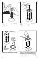
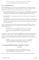
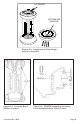
In replacing Top Gasket, make certain it is properly centered in the recess provided in
top fl ange of FYRITE Body (See Figure 24). When installing plastic Top Cap Assem-
bly, be sure that assembly is centered on Top Gasket.
To remove Top Cap Assembly or replace Top Cap, Plunger Valve, or Plunger Tip Gas-
ket, use the procedure as outlined in Section 6.3.
When replacing Plunger Tip Gasket, simply depress Plunger Valve against its spring
limit and strip old Gasket from the end of Plunger Valve.
Before assembling new Gasket, wet inside surface of Tip Gasket, then force it over the
end of Plunger Valve (after depressing Plunger Valve against the spring limit).
Make certain that new Tip Gasket is seated uniformly against the mating surface in
plastic Top Cap.
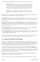
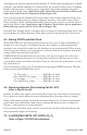
To replace Diaphragm, stand FYRITE upside down, remove 4 screws and metal Bot-
tom Cap.
Refer to Figure 25a. Remove old Diaphragm and center new replacement with the
lettering facing you, so that after the FYRITE Bottom Cap is installed the letters will
face up into its recess. Center Bottom Cap Assembly in Body Recess and reinstall 4
screws, observing same precautions in tightening as outlined in Section 6.3.
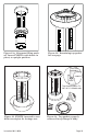
To replace Body, remove the 4 hex head Bezel screws and 4 Bezels. Install Bezels on
new Body.
NOTE: Make certain the rubber bezel gaskets are properly
seated and clamped between bezel and body as shown in Figure
25.
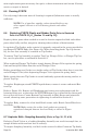
6.7 Aspirator Bulb - Sampling Assembly (Refer to Figs. 26, 27, & 28)
Defective Check Valves or a leaking Sampling Assembly can result in sample loss, or
sample dilution with resultant loss of accuracy.
To inspect Sampling Assembly, seal hole in the center of rubber Connector Tip fi rmly