
Specifications

Instruction 0011-9026 Page 9
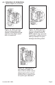
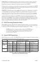
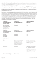
Figure 12. When plunger
valve is depressed, a gas
sample is pumped through
top reservoir with center
bore is sealed off.
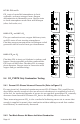
Figure 13. When plunger
valve is released, the gas
sample is locked into FY-
RITE and the top reservoir
is opened to center bore so
that gas sample can pass
through absorbing fl uid.
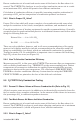
Figure 14. Absorption of
gas sample by fl uid cre-
ates suction, which causes
diaphragm to fl ex up and
fl uid to rise in center bore
to replace gas absorbed.
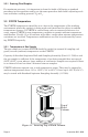
4.0 PRINCIPLE OF OPERATION
(Refer to Figures 12, 13, and 14)