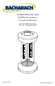
INSTRUCTION 0011-9026 FYRITE® Gas Analyzer CO2 and O2 Indicators Operation/Maintenance Rev. 12 – December 2012 20 16 %CO2 12 8 4 0 ® Printed in U.S.A.
WARRANTY Bacharach, Inc. warrants to Buyer that at the time of delivery this Product will be free from defects in material and manufacture and will conform substantially to Bacharach Inc.’s applicable specifications. Bacharach’s liability and Buyer’s remedy under this warranty are limited to the repair or replacement, at Bacharach’s option, of this Product or parts thereof returned to Seller at the factory of manufacture and shown to Bacharach Inc.
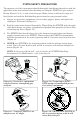
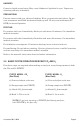
FYRITE SAFETY PRECAUTIONS The operator (s) of this instrument should thoroughly familiarize themselves with the applicable safety precautions before handling or using the FYRITE for gas analysis. Review Figures 1a,1b, 1c and 1d on this page. Make certain to follow the steps outlined below and read the fluid handling precautions for your personal safety. 1) Always use protective equipment such as safety goggles, gloves, and protective clothing as illustrated in Figure 1a.
TABLE OF CONTENTS 1.0 DESCRIPTION................................................................................................................................................1 2.0 FYRITE INSPECTION BEFORE AND DURING TEST ..............................................................................1 2.1 Pre-Operational Check .......................................................................................................................1 2.2 FYRITE FLUID HANDLING PRECAUTIONS........................
INSTRUCTIONS 0011-9026 OPERATION/MAINTENANCE BACHARACH FYRITE MODELS CO2 and O2 INDICATORS 1.0 DESCRIPTION (Refer to Figure 1) The FYRITE employs the well-known “Orsat” method of volumetric analysis involving chemical absorption of a sample gas, such as carbon dioxide or oxygen. The reagent used to absorb carbon dioxide (CO2) is potassium hydroxide (dyed red), and chromous chloride (blue) is the absorbent for oxygen (O2).
(b) FYRITE Fluid Strength To check fluid strength. NOTE: When repeating procedures as outlined in Section 3.0 Steps 7 through 9 (absorbing and reading percent O2 and absorbing and reading percent CO2) and before venting FYRITE to atmosphere for next sample, if the reading increases by more than 1/2 percent for either CO2 or O2, replace the fluid. It is often desirable to check fluid strength before taking the FYRITE to a location where it will be used.
HAZARDS Corrosive liquid causes burns. May cause blindness if splashed in eyes. Vapors are irritating and may be harmful. PRECAUTIONS Prevent contact with eyes, skin and clothing. Wear eye protection and gloves. Do not vent instrument until fluid has drained from top well. Do not vent instrument (FYRITE) in inverted position. FIRST AID For contact with eyes: Immediately flush eyes with water 20 minutes. Get immediate medical attention. For contact with skin: Immediately flush skin with water 20 minutes.
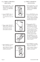
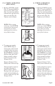
CO2 FYRITE OPERATION (RED FLUID) O2 FYRITE OPERATION (BLUE FLUID) 1. Hold upright (Fig. 1) and away from face. Depress Plunger Valve (momentarily) to vent FYRITE, and release. 1. Hold upright (Fig. 1) and away from face. Depress Plunger Valve (momentarily) to vent FYRITE, and release. 2. Invert FYRITE (Fig. 2). Hold at slight angle to drain fluid into top reservoir. Figure 1 2. Invert FYRITE (Fig. 2) to absorb O2 drawn into FYRITE whenever Plunger Valve is depressed).
CO2 FYRITE OPERATION (RED FLUID) O2 FYRITE OPERATION (BLUE FLUID) 5. Holding FYRITE upright (Fig. 5), loosen locknut at rear of scale. Slide scale (Fig. 5a) until top of fluid column lines up with zero line on scale (Fig. 5b). Tighten scale locknut. 5. Holding FYRITE upright (Fig. 5), loosen locknut at rear of scale. Slide scale (Fig. 5a) until top of fluid column lines up with zero line on scale (Fig. 5b). Tighten scale locknut.
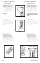
CO2 FYRITE OPERATION (RED FLUID) O2 FYRITE OPERATION (BLUE FLUID) 7. Absorb sample gas into FYRITE by inverting until fluid drains into top reservoir (Fig. 7). Then turn upright (Fig. 8) to drain fluid into bottom reservoir. Repeat this step three (3) more times (four complete inversions total). 7. Absorb sample gas into FYRITE by inverting until fluid drains into top reservoir (Fig. 7). Then turn upright (Fig. 8) to drain fluid into bottom reservoir. Repeat this step once. Figure 7 8.
10. This step completes CO2 or O2 FYRITE gas sample analysis. A few points to remember when reading the FYRITE: (a) FYRITE accuracy is within ±1/2% CO2 or O2 compared to actual value. (b) Always handle FYRITE by fins to ensure body heat is not absorbed by fluid. (c) A delay in reading of 5 or 10 seconds may decrease accuracy of reading slightly but longer delays may cause substantial error.
3.2.1 Draining Fluid Droplets For maximum accuracy, it is important to form the habit of following a standard procedure in this operation and to use the same procedure both before adjusting scale zero and before reading percent CO2 or O2 . 3.3 FYRITE Temperature The FYRITE temperature should be at or close to the temperature of the working environment where the analysis is being made and should not be subject to sudden temperature changes.
4.0 PRINCIPLE OF OPERATION (Refer to Figures 12, 13, and 14) Figure 12. When plunger valve is depressed, a gas sample is pumped through top reservoir with center bore is sealed off. Figure 13. When plunger valve is released, the gas sample is locked into FYRITE and the top reservoir is opened to center bore so that gas sample can pass through absorbing fluid. Figure 14.
To make a test with the FYRITE, the metal Sampling Tube at one end of Sampling Assembly Hose is inserted into the gas to be analyzed. The rubber Connector Plug at the other end of the Rubber Hose is then firmly pressed down on the spring-loaded Valve of the instrument (See Figure 12). This simultaneously opens a passage into the Top Reservoir and seals off the center bore. Next, a sample of the gas is pumped into the Top Reservoir by squeezing the rubber Aspirator Bulb.
FYRITE CO2 refill fluid may develop a white insoluble precipitate upon aging. The precipitate does not affect fluid performance in any way, but if present, should be filtered out to prevent adherence to internal surfaces of the FYRITE. To filter, place a clean piece of thin cloth or netting loosely over the open CO2 FYRITE and slowly pour refill contents into top reservoir. Before disposing of cloth, rinse thoroughly with water.
0-7.6% CO2 or O2 CO2 tests of controlled atmospheres in fruit, vegetable, and meat storage rooms. Oxygen determination in flammable gases. Oxygen tests to check atmospheres made inert with nitrogen (silos, fuel tanks, etc.) 0-20% CO2 or 0-21% O2 Flue gas combustion tests, oxygen deficiency tests, and CO2 tests of heat treating atmospheres. Checking oxygen concentrations in hydrogen-cooled generators and oil-sealed inert-gas transformers.
Excess combustion air is heated and carries some of this heat to the flue where it is wasted. The FYRITE CO2 Analyzer is used to adjust combustion excess air to a minimum (maximum CO2), which will permit clean efficient combustion. Calculation of combustion efficiency is possible (assuming complete combustion) if percentage of CO2 and net temperature of combustion products are known. 5.4.
Proper O2 content for any fuel fired is the lowest O2 value that will ensure complete, clean combustion with adequate safety margin for variations in fuel, draft, atmospheric conditions, and mechanical wear. Consult manufacturer of heating equipment or local authorities for specific recommendations. Figure 15 illustrates the relationship between CO2, excess air and oxygen for gas and oil. For guidance, it should be added that modern boilers are capable of 80% or greater combustion efficiency.
PERCENT EXCESS AIR Figure 15. Relation between Oxygen, CO2 and excess air in flue gases for Natural Gas and Fuel Oil. THEORETICAL EXCESS AIR CURVE STOICHIOMETRIC MIX Figure 16. CO2 measurements alone do not determine combustion air setting when firing gaseous fuels.
As a rule of thumb, background gases/vapors may be present in concentrations up to 1/2% by volume (5000 ppm) before they present a significant interference problem to the CO2 or O2 FYRITE (20/21% ranges). An exception exists with the action of ammonia on Oxygen FYRITE Fluid. Ammonia neutralizes the acidic solution of chromous chloride, and therefore use of the O2 FYRITE with even trace amounts of ammonia in the backgrounds is not advised unless suitable filters are used.
Figure 17. Checking CO2 of gas designed furnace (sampling tube inserted through draft diverter; flue gas temperature test can be made at same point). 5.7 General FYRITE Applications It is only possible to specify a few general rules for such applications. Where possible, sample should be obtained at a point where the gases are well mixed to a uniform composition. Where this is impossible; it will be necessary to average a number of measurements taken at different locations to obtain representative average.
The gas concentration read on the FYRITE is directly dependent upon the mass of air in the sample. The aspirator bulb used in the FYRITE is a constant-volume pump, not a constant-mass pump. Altitude, therefore, affects the FYRITE reading due to the air’s density changing with altitude, thus requiring higher CO2 or O2 concentrations to reach the same mark on the scale. Use the following table to find the altitude correction (e.g., add the correction to the reading to get the correct concentration).
Refer to Figure 19. To remove excess fluid, insert small diameter glass tube into FYRITE fluid through the small center FYRITE bore (with Top Cap Assembly removed). Seal open end of glass tube with finger and dip out fluid with glass tube until FYRITE fluid is at proper level. Avoid unnecessary exposure of O2 fluid to air since it will rapidly absorb O2 and become exhausted. 6.2 Checking FYRITE Fluid Strength 6.2.
20 20 16 16 12 12 8 %CO2 4 8 %CO2 4 0 0 ® ® Figure 18. Increasing FYRITE fluid to proper level. Figure 19. Decreasing FYRITE fluid to proper level TOP GASKET 20 16 12 8 %CO2 4 0 ® TOP CAP/ PLUNGER VALVE ASSEMBLY 20 16 12 8 %O2 4 0 ® OVAL HEAD SCREWS TOP CAP RING WITH GASKET Figure 20. Removing top gasket. Page 20 Figure 21. Flushing FYRITE with a stream of O2 free, inert gas (Also see Fig. 21a for alternate method).
accuracy don’t forget to saturate filter saturator wool packing as such gas standards are usually supplied “bone dry”. 6.2.2 O2 FYRITE Fluid Only Fresh FYRITE fluid will absorb all O2 from approximately 100 samples containing 10% O2. After completing test (as outlined in Section 3.0 Steps 1 through 9) O2 FYRITE Fluid strength can be checked by performing steps outlined below: 1.
Drain old fluid from FYRITE and rinse all parts in clean, lukewarm water. NOTE: FYRITE fluid is corrosive to skin, clothing, some metals, and painted or lacquered surfaces. Dispose of these fluids in accordance with Local, State and Federal Laws. If draining into a porcelain sink is permitted, keep water faucet turned on while draining and flush for at least 1/2 minute afterwards. NOTE: Examine top gasket for warpage, if distorted as shown in Figure 22, replace gasket with part # 11-0143 before proceeding.
® 0 8 %CO2 4 12 16 20 20 16 12 8 %CO2 4 0 Figure 21a. Alternate filling method. Invert FYRITE (with bottle in place) to upright position. Figure 22. Examining top gasket for warpage. TOP CAP ASSEMBLY GASKET 20 16 BODY ® 12 8 %CO2 4 0 0 Top Gasket used in 7%, 20% & 21% Models only ® 8 %CO2 4 12 16 20 Figure 23. FYRITE inverted in test disk (overnight) for leakage test. Instruction 0011-9026 Figure 24. Top gasket properly centered in top flange of body.
mine replacement parts necessary for repair, or drain instrument and return if factory service or repair is desired. 6.5 Cleaning FYRITE Use only soapy lukewarm water if cleaning is required (lukewarm water is usually sufficient). NOTE: Use of gasoline, naptha, carbon tetrachloride or any other organic solvent or oil will destroy plastic and rubber parts. 6.6 Replacing FYRITE Plastic and Rubber Parts (Refer to Illustrated Parts List FYRITE CO2/O2 [Section 7.0 and Fig.
LETTERING BOTTOM CAP (RECESS) ® 0 4 %CO2 8 12 16 20 Figure 25a. Replacement Diaphragm properly installed. Figure 25. Locating Bezel Rubber Gaskets. Instruction 0011-9026 Figure 26. FYRITE Sampling Assembly; Locating Inlet/Outlet Check Valves.
with finger and squeeze Aspirator Bulb (Figure 27). Bulb should remain firm. If Bulb collapses, check Bulb and Hose to Connector Tip for cracks or other source of leakage. Replace defective parts. If there are no apparent leaks in the Sampling Assembly, replace Inlet Check Valve. Small hole end of Inlet Check Valve fits in Hose and large hole end fits in the Aspirator Bulb (Figure 26). Now seal end of metal Sampling Tube with finger, and collapse Aspirator Bulb. (Figure 28).
RUBBER CONNECTOR TIP (HOLD FINGER HERE) ASPIRATOR BULB SHOULD REMAIN FIRM WHEN SQUEEZED Figure 27. Testing Sampling Assembly (outlet side) for leaks. CHECK FOR BULB INFLATION AFTER SQUEEZING SAMPLING TUBE END (HOLD FINGER HERE) Figure 28. Testing Sampling Assembly (inlet side) for leaks. Figure 29. Removing End Plugs from Saturator Filter Tube.
Figure 30. Wrapping Replacement Filter Material. Figure 31. Wet Filter Material then squeeze out excess water. Figure 32. Installing wetted Filter Material into Saturator Tube.
Part # Description 11-0102 11-0188 11-0110 11-0109 Bezel Oval Head Screw Bezel Screw Top Cap Ring Gasket (Optional, Part of 11-0136) 4 8 4 1 11-0105 02-3690 11-0021 11-0126 11-0132 11-0019 11-0026 11-0020 11-0136 11-0143 11-0140 Scale Screw Scale Screw Nut Diaphragm Bottom Cap Top Cap Valve Plunger Valve Plunger Spring Valve Plunger Gasket Top Cap Ring with Gasket Top Gasket (7%, 20% & 21% Models only) FYRITE Body (All Models except 7.
7.1 FYRITE ILLUSTRATED PARTS 11-0062 11-0019 05-5169 11-0102 11-0026 11-0188 05-5155 11-0136 11-0188 11-0109 11-0132 11-0143 (7%, 20%, and 21% Models Only) 11-0102 11-0020 11-0110 05-5134 02-3690 11 -01 05-5134 05 11-0110 11-0140 11-0102 11-0110 11-0154 11-0021 11-0126 11-0110 11-0102 11-0188 Figure 33. FYRITE parts breakout.
7.2 PARTS LIST FOR FYRITE SAMPLING ASSEMBLIES STANDARD SAMPLING ASSEMBLY Part No. 11-7029 Gases saturated with water vapor (combustion products). Dry gases when filter material is wetted.
Current Part # Former List # 11-0152 11-0156 11-0118 11-0165 19-5004 11-0120 11-0138 11-0119 11-0180 11-0130 11-0106 11-0161 11-0179 11-0121 11-0181 10-0019 10-0029 10-0020 10-0030 19-9004 10-0022 10-0023 10-0024 10-0025 10-0026 10-0027 10-0040 10-0042 10-0033 10-0032 Page 32 Description # Req'd Connector Tip with Tube Rubber Tubing, 10' Length Rubber Tubing, 6" Length Filter Tube, Aluminum Gas Collecting Bladder with Orifice Aspirator Bulb Inlet/Outlet Valve (Red) Rubber Tubing, 3' length Filter Nip
Notes Instruction 0011-9026 Page 33
Notes Page 34 Instruction 0011-9026
Notes Instruction 0011-9026 Page 35
Bacharach, Inc. 621 Hunt Valley Circle, New Kensington, PA 15068 Phone: 724-334-5000 • Fax: 724-334-5001 • Toll Free: 800-736-4666 Web: www.mybacharach.com • E-mail: help@mybacharach.