LS8000/2 LEVEL SWITCH OWNERS MANUAL ♦ INSTALLATION ♦ CALIBRATION ♦ TROUBLESHOOTING ♦ WARRANTY BABBITT INTERNATIONAL, INC. P.O.
TABLE OF CONTENTS Page 1. Description -------------------------------------------------------------- 1 A. General Description B. Specifications -------------------------------------------- 2 C. Ordering Information 2. Theory of Operation ----------------------------------- 1 ----------------------------------- 2 -------------------------------------------- 3 3. Installation-------------------------------------------------------------- 3 A.
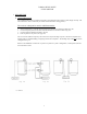
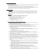
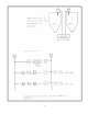
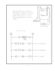
LS8000/2 DUAL POINT LEVEL SWITCH 1. DESCRIPTION A. General Description The LS8000/2 dual point level switch is designed to sense material at two points in a tank, hopper or sump. The unit consists of a receiver which may be remote mounted from the sensing probe(s). The receiver is designed to work in 4 different modes: 1. 2. 3. 4. Sense 2 points along a vertically mounted probe and maintain a level between them. (Fig 1A) Control 2 separate probes in the same tank and maintain a level between them.
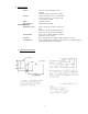
B. Specifications Electrical Power: Output: Fuse: RF Frequency: Environmental Hazardous Area: Temperature: Pressure: Construction: 115 VAC (±15%) 50/60 Hz. 3 watts, standard. (12 VDC, 24 VDC or 230 VAC optional) 3 relays, each with 1 form C contact, SPDT, 10 amp resistive at 115 vac, 8 amp at 220 VAC, 5 amp at 30 VDC On board, 250 mA Approximately 700 KHz Class I, Group C & D, Class II, Group E, F and G Receiver: open printed circuit board can be put in enclosure as required by application.
2. THEORY OF OPERATION The LS8000/2 employs a radio frequency (RF) balanced impedance bridge circuit to detect the level of material along a vertically mounted probe. As the fluid level rises along the probe, the output of the bridge changes proportionally to the fluid level. The setpoint potentiometers determine at what level the circuit detects the low and high setpoints. The receiver may also control 2 independent probes in the same or different tanks.
4
5
6
7
8
9
10
11
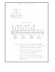
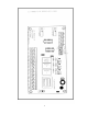
C. Installing the Receiver The receiver is a printed circuit board measuring 3”x6”. It is mounted in a plastic snap track that is provided with each unit. The snap track can be mounted in existing control panels or enclosures may be ordered from the factory. 1) Attach the snap track to the panel back pan or other surface using 2 small screws or a suitable adhesive. 2) Snap the LS8000/2/R receiver card into the snap track. 3) Connect shielded cable to the 3 terminals marked GND, SIG, V+.
“POR” is used to select the “POWER-ON-RESET” mode of the LS8000/2 if the supply voltage should be interrupted while the fluid level is between the low and high setpoints. If the unit should lose power, and the level is between the setpoints, the LS8000/2 can not “remember” if it was filling or emptying at the time of power loss. By properly setting “POR” for your application, the relay will either energize or de-energize when power is restored to the unit.
5. MAINTENANCE AND TROUBLESHOOTING No routine maintenance is required other than to keep the interior of the unit clean and free of dirt, moisture and other contaminants. The LS8000/2 consists of three main sub-assemblies. These are the enclosure with the antenna probe, the transmitter module and the receiver card. The following troubleshooting guide will assist in determining how to correct most of the problems, which may occur in the field.
6. WARRANTY All components of the LS8000/2 are warranted to be free from defects in material and workmanship for a period of two years from the date of purchase. This warranty applies to general purchaser and to components installed, serviced and operated according to instructions. Babbitt International, Inc. will repair or replace, at its option, FOB at its plant or any other location designated, any part which proves to be defective in manufacture or workmanship.