LS7000 LEVEL SWITCH OWNERS MANUAL ♦ INSTALLATION ♦ CALIBRATION ♦ TROUBLESHOOTING ♦ WARRANTY BABBITT INTERNATIONAL, INC. P.O.
TABLE OF CONTENTS 1. Description ------------------------------------------------------A. General Description Page 1 ---------------------------------- 1 B. Specifications ------------------------------------------- 1 2. Theory of Operation ------------------------------------------- 2 3. Installation------------------------------------------------------------- 2 A. Inspection and Operation Check ------------------------- 2 B. Physical Installation ------------------------------------------- 2 C.
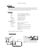
LS7000 LEVEL SWITCH 1. DESCRIPTION A. General Description The LS7000 is a point level switch that detects the presence or absence of material in a bin, silo, tank or other container. The basic unit is made up of a solid stainless steel probe attached to an explosion proof housing. Inside the explosion proof housing are all calibration adjustments and sensing electronics. The unit is calibrated in the absence of material and an internal relay changes state when material is detected. B.
2. THEORY OF OPERATION The LS7000 employs a radio frequency (RF) balanced impedance bridge circuit to detect if the probe is in contact with the material that is to be sensed. When material is not in contact with the probe, the bridge is balanced by turning the adjustment pot to find the threshold where the red led goes out. When material is in contact with the probe, the bridge becomes unbalanced and the comparing circuit realizes the change. This causes the relay to change state. 3.
a) For dry materials, mount the LS7000 in the top of the vessel whenever possible. (This allows you to lengthen the probe if necessary.) b) Avoid mounting the LS7000 near the product inlet, vent return lines, dust collectors and vessel discharge openings on dry materials. Turbulence around these areas can cause erratic detection unless the probe is long enough. On old installations it might be wise to fill the vessel first to determine the length or location of the probe.
4
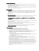
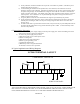
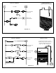
TYPICAL WIRING L1 APPLICATION HIGH LEVEL ALARM 115 VAC L1 L2 LS7000 L2 FAIL SAFE HIGH SELECTED. G NC1 R HIGH LEVEL ALARM LIGHT. C1 NO1 FIGURE 7.4 TYPICAL WIRING L1 APPLICATION 115 VAC L2 AUTOMATIC FILLING OF TANK. (WHEN LEVEL FALLS TO POINT “A”, A PUMP COMES ON TO FILL TO POINT “B”, THEN TURNS OFF.) L1 LS7000 ”A” L2 FAIL SAFE LOW SELECTED. G L1 LS7000 “B” L2 FAIL SAFE HIGH SELECTED. “B” G LS7000 A C1 NC1 LS7000 B C1 NO1 PUMP PUMP MOTOR STARTER PUMP AUX.
TYPICAL WIRING L1 APPLICATION 115 VAC L1 L2 LS7000 L2 FAIL SAFE HIGH SELECTOR, ON, DELAY SET FOR 2 SECONDS G C1 NC1 HIGH LEVEL ALARM USING THE TIME DELAY TO IGNORE SPLASHING OR WAVE ACTION. (TIME ON, INSTANT OFF) R HIGH LEVEL ALARM LIGHT. “A” WHEN THE FLUID REACHES POINT “A”, IT MUST REMAIN THERE FOR 2 SECONDS BEFORE THE INDICATOR LAMP WILL COME ON. NOTE: PLEASE REVIEW FAIL SAFE SELECTION INSTRUCTIONS, SECTION IV B. FIGURE 7.
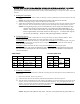
4. CALIBRATION PLEASE READ THE ENTIRE CALIBRATION PROCEDURE BEFORE CALIBRATING THE LS7000. If no time delay is required, turn the time adjustment pot completely CCW and set S1 down, S2 up. The potentiometer has 18 turns and freewheels at the end of its travel without damage. You may hear “clicks” at the end of travel. A. Setting the Time Delay 1) Setting the timing mode, either on delay or off delay is done by positioning S3 and S4 as shown in the chart below.
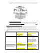
Every LS7000 has a diagram inside the screw cover to serve as a reminder to those who have calibrated the unit before. This shows the calibration adjustments and indicators. This diagram is reproduced below. SPECIAL CALIBRATION NOTES: For some products, the LS7000 can be calibrated with product touching the probe. To do this, turn the sensitivity adjust pot CW until the red LED just comes on and continue CW for 1/8 to ¼ of a turn. Always check to see if the unit resets in the absence of product. 5.
Unit will not detect material. Improper calibration. Unit will not stay in calibration. Relay operates properly, but no signal at terminals. Antenna lead not plugged into probe. Unit was calibrated with material touching probe. Poor grounding of unit to vessel. Burned or broken lands on the printed circuit board. Bad relay contacts. See calibration instructions, section 4. Plug antenna lead into probe. Be sure material is not touching probe and recalibrate. Provide secure ground connection.