LS7000/2 DUAL POINT LEVEL SWITCH OWNERS MANUAL ♦ INSTALLATION ♦ CALIBRATION ♦ TROUBLESHOOTING ♦ WARRANTY BABBITT INTERNATIONAL, INC. P.O.
TABLE OF CONTENTS Page 1. Description -------------------------------------------------------------- 1 A. General Description B. Specifications -------------------------------------------- 1 C. Ordering Information 2. Theory of Operation ----------------------------------- 1 ----------------------------------- 1 -------------------------------------------- 2 3. Installation-------------------------------------------------------------- 2 A.
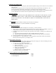
LS7000/2 LEVEL SWITCH 1. DESCRIPTION A. General Description The LS7000/2 dual point level switch is designed to automatically maintain a level between two points along a vertically mounted probe. The two setpoints are adjustable over the entire length of the probe. The LS7000/2 can be used to automatically fill a tank, or automatically pump down a sump. A single relay, DPDT, 5 amp, is used for control.
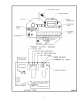
2. THEORY OF OPERATION The LS7000/2 employs a radio frequency (RF) balanced impedance bridge circuit to detect the level of material along the probe. As fluid level rises along the probe, the output of the bridge changes proportionally to the fluid level. The setpoint potentiometers determine at what level the circuit detects the low and high setpoints. An on-board dip switch (S2) determines automatic fill or automatic empty operation.
3
4
5
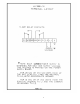
4. CALIBRATION PLEASE READ THE ENTIRE CALIBRATION PROCEDURE BEFORE CALIBRATING THE LS7000/2. A. Setting S1 and S2 Switches S1 and S2 are the dip switches on the LS7000/2 sensing card. S2 selects automatic fill or automatic empty. “AUTOMATIC FILL” is when the relay energizes below the low setpoint and de-energizes below the high setpoint. “AUTOMATIC EMPTY” is when the relay energizes at the high setpoint and de-energizes below the low setpoint. The green LED indicates relay status.
C. Calibrate the High Setpoint As a rule of thumb, clockwise (CW) rotation of the pot lowers the setpoint; counter-clockwise (CCW) rotation of the potentiometer raises the setpoint. 1) Raise the fluid level to where you want the high setpoint to be on the probe. 2) Observe the high red LED. If it is off, go to step 4. 3) If the high red LED is on, turn the high adjustment pot CCW until the high red LED goes out. 4) Turn the high adjustment pot CW until the high red LED just comes on.
6. WARRANTY All components of the LS7000/2 are warranted to be free from defects in material and workmanship for a period of two years from the date of purchase. This warranty applies to general purchaser and to components installed, serviced and operated according to instructions. Babbitt International, Inc. will repair or replace, at its option, FOB at its plant or any other location designated, any part which proves to be defective in manufacture or workmanship.