LS6000 LEVEL SWITCH OWNERS MANUAL ♦ INSTALLATION ♦ CALIBRATION ♦ TROUBLESHOOTING ♦ WARRANTY BABBITT INTERNATIONAL, INC. P.O.
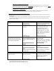
TABLE OF CONTENTS Page 1. Description ------------------------------------------------------- 1 A. General Description --------------------------------------- 1 B. Specifications ----------------------------------------------- 1 2. Theory of Operation/Ordering Information 3. Installation ---------------- 2 ------------------------------------------------------------- 2 A. Inspection and Operation Check -------------------------- 2 B.
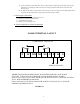
LS6000 LEVEL SWITCH 1. DESCRIPTION A. General Description The LS6000 is a point level switch that detects the presence or absence of material in a bin, silo, tank or other container. The basic unit is made up of a solid stainless steel probe attached to an explosion proof housing. Inside the explosion proof housing are all calibration adjustments and sensing electronics. The unit is calibrated in the absence of material and an internal relay changes state when material is detected. B.
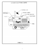
2. THEORY OF OPERATION The LS6000 employs a radio frequency (RF) balanced impedance bridge circuit to detect if the probe is in contact with the material that is to be sensed. When material is not in contact with the probe, the bridge is balanced by turning the adjustment pot to find the threshold where the red led goes out. When material is in contact with the probe, the bridge becomes unbalanced and the comparing circuit realizes the change. This causes the relay to change state. 3.
d) On dry product that flows like water (starch), when using the LS6000 to stop the flow by means of a butterfly valve or knifegate, make sure the probe is long enough to allow time to close these slow moving valves. e) In small vessels where a good location is hard to find, it may be necessary to put a baffle plate between the probe and the product inlet to keep product off of the probe as it fills. C. Removing the Electronics 1) 2) 3) 4) Disconnect supply power at main power source.
4
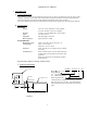
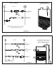
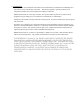
TYPICAL WIRING L1 APPLICATION HIGH LEVEL ALARM 115 VAC L1 L2 LS6000 L2 FAIL SAFE HIGH SELECTED. G NC1 R HIGH LEVEL ALARM LIGHT. C1 NOTE: PLEASE REVIEW FAIL SAFE INSTRUCTIONS, (SEC. 4A) FIGURE 6.4 TYPICAL WIRING L1 APPLICATION 115 VAC L1 L2 LS6000 L2 “A” FAIL SAFE LOW SELECTED. L2 “B” FAIL SAFE HIGH SELECTED. AUTOMATIC FILLING OF TANK. (WHEN LEVEL FALLS TO POINT “A”, A PUMP COMES ON TO FILL TO POINT “B”, THEN TURNS OFF.
4. CALIBRATION PLEASE READ THE ENTIRE CALIBRATION PROCEDURE BEFORE CALIBRATING THE LS6000. A. Fail Safe Selection The fail safe feature provides a “false alarm” in case of power outage or major component failures. When properly selected, the fail safe feature can protect equipment or alert you of a unit failure. Fail Safe High (FSH) means that the relay is energized when NO PRODUCT is touching the probe. When product comes into contact with the probe, the relay is de-energized.
SPECIAL CALIBRATION NOTES: For some products, the LS6000 can be calibrated with product touching the probe. To do this, turn the sensitivity adjust pot CW until the red LED just comes on and continue CW for 1/8 to ¼ of a turn. Always check to see if the unit resets in the absence of product. INTERFACE CALIBRATION For applications such as an oily water interface, the unit should be calibrated in the less electrically conductive fluid (oil) and the unit will then “ignore” the oil, but sense the water. 5.
6. WARRANTY All components of the LS6000 are warranted to be free from defects in material and workmanship for a period of two years from the date of purchase . This warranty applies to general purchaser and to components installed, serviced and operated according to instructions. Babbitt International, Inc. will repair or replace, at its option, FOB at its plant or any other location designated, any part which proves to be defective in manufacture or workmanship.