
Installation Manual

INSTALL CENTER SECTION
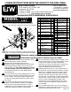
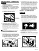
Position Center Section. Push the front cross
member forward and the rear cross member rearward
so that there is room between them for the center
section. With the square holes of the latch
mechanism on the driver side, lift the center into place
as shown in Figure C1.
1.
Failure to follow the bolt tightening sequence as
listed above may result in the hitch components
being misaligned which could affect the
performance of the hitch, or result in property
damage, or serious injury.
Install Hardware.
Attach the center to the front cross
member by passing 1/2" x 4" bolts. Through the
washer plate, and cross member and into the center
section. Secure the bolts with flat washers, lock
washers, and nuts. Next, attach the center to rear
cross member with 1/2" x 1−1/2" bolts, flat washers,
and lock washers, see Figure C2. Do not fully tighten
hardware connections at this time.
Lifting Device. A lifting device may be used to
suspend the hitch below the truck bed in the correct
position for securing the hardware. However, it is not
needed to force center section against the bottom of
the truck bed since this hitch does not contact the bed.
SECURE HITCH
2.
3.
Step 3:
Tighten the 1/2" x 1−1/2" bolt with the thread
locker pre−applied between the passenger front cross
member bracket and the passenger inside side plate.
Next tighten the 1/2" x 1−1/2" bolt with thread locker
between the driver rear cross member bracket and the
driver inside side plate, see Figure D1. Examine the
4" hole again to be sure the socket is still centered in
the hole.
Step 2: Make sure all other hardware connections are
tight enough to hold mating surfaces of parts flush but
not tight enough to restrict movement for adjustment.
Examine the socket from inside the truck bed through
the 4" hole. Adjust the position of the hitch until the
hitch cross members are parallel to the bed cross
members and the socket is centered within the hole.
Step 1: First, tighten the hardware attaching the cross
members to the center section and each cross
member bracket, see Figure D1
Step 4: Once the hitch is properly located, tighten the
remaining two bolts to the inside side plates. Then
tighten the bolts with thread locker, that attach the
outside side plates and the cross member brackets.
Finally tighten the 5/8" bolts holding the side plates to
the frame, see Figure D1.
Step 5: Once hitch is tight, torque all 5/8" hardware to
150 ft. lbs., and all 1/2" hardware to 100 ft. lbs.
1.
2.
3.
4.
5.
IMPORTANT:
The hitch must be square in the truck.
If the latch pin is not parallel with the axle, certain
accessories to the Turnoverball hitch will not be
square with the truck.
PAGE 4 of 6
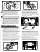
Figure C1: Bottom of truck frame looking up at hitch installation area.
Figure C2: Bottom of truck frame looking up
from the back of truck towards the cab
Figure D1: Bottom of truck frame looking up at hitch installation.
STEP 1 (1st)
STEP 1 (1st)
STEP 3 (3rd)
STEP 3 (2nd)
STEP 4 (4th)
STEP 4 (4th)
STEP 4 (5th)
STEP 4 (5th)
STEP 4 (5th)
STEP 4 (5th)
STEP 4 (6th)
SIDEPLATES (NOT VISIBLE)
LATCHING
MECHANISM