
Installation Manual
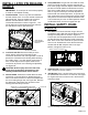

INSTALL LATCH PIN RELEASE
HANDLE
IMPORTANT: The latch pin will not function properly
if handle is not installed correctly.
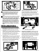
Position handle. There is very little room between
the bed and the frame. From the outside of the driver
side wheel well, Pass the handle over the frame
between the bed stiffener and the rear driver
crossmember bracket as shown in figure E1. The
handle will have to be pushed toward the cab once
the end with the holes is past the frame.
1.
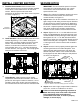
Lock out Latch Pin.
Retract the latch pin of the
center section and lock it out by pushing the
mechanism toward the cab, see Figure E2. In order to
prevent the mechanism from latching while attaching
the handle, place a 1/4" allen wrench, thick piece of
wire, or other object into the space shown on the
mechanism to prevent it from latching unexpectedly,
see Figure E2.
2.
Secure Handle.
Position the handle above the latch
mechanism, and insert the 5/16" bolts through the
holes in the latch mechanism. Secure these bolts with
the 5/16" locking flange nuts, see Figure E2. Remove
the object that is preventing the mechanism from
latching and allow the pin to latch.
3.
Verify Clearance.
The general area under the truck
where the handle operates contains several brake
lines, wires, plugs, and other objects. Retract the latch
pin with the handle attached and observe the travel
path of the handle. Make sure that its travel path is
clear. It may be necessary to relocate objects that
interfere with the handle’s operation. To operate the
latch mechanism from the wheel well, pull the handle
away from the truck frame and push toward the cab.
This will hold the pin in the un−latched position. Move
handle toward rear of truck to engage latch pin.
4.
CAUTION: Serious injury can occur due to the
pinch point located at the intersection of the
latching mechanism and the center section.
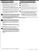
INSTALL SAFETY CHAIN
U−BOLTS
Drill Holes. From under the bed, using a drill and
small drill bit, drill a pilot hole into the bed in 4 places
through the safety holes as shown in Figure F1.
These holes must be perpendicular to the surface of
the bed. Examine the holes from inside of the truck
bed. Each set of holes should be 2" apart and each
hole of a set should be the same distance from the
nearest bed rib. With the pilot holes in the right
position, enlarge the holes to 1/2"
1.
Install U−bolts.
From the top side of the truck bed,
drop a U−bolt in each set of holes.
2.
Add Springs.
Place a conical spring over each leg of
the U−bolts and secure with a 1/2" lock nut, see Figure
F2. Tighten the lock nut until the nut is flush with the
end of the U−bolt.
3.
PAGE 5 of 6
Figure E1: Driver Side Wheel Well.
Figure E2: View looking up at latch mechanism of center section.
Figure F2: View looking up at U−bolt installation locations in center section.
Figure F1: Bottom of truck bed looking up at hitch installation.
BED STIFFENER
SPACE FOR 1/4" ALLEN WRENCH OR OTHER
OBJECT TO KEEP HANDLE LATCHED OUT.
SAFETY CHAIN LOCATIONS
LATCH PIN
REAR DRIVER
CROSSMEMBER
BRACKET