
Installation guide
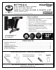
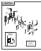
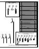
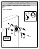
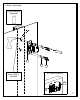
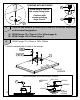
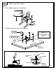
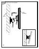
Table Of Contents
- BT7524 ASSEMBLY LEAFLET PAGE 1
- BT7524 ASSEMBLY LEAFLET PAGE 2
- BT7524 ASSEMBLY LEAFLET PAGE 3
- BT7524 ASSEMBLY LEAFLET PAGE 4
- BT7524 ASSEMBLY LEAFLET PAGE 5
- BT7524 ASSEMBLY LEAFLET PAGE 6
- BT7524 ASSEMBLY LEAFLET PAGE 7
- BT7524 ASSEMBLY LEAFLET PAGE 8
- BT7524 ASSEMBLY LEAFLET PAGE 9
- BT7524 ASSEMBLY LEAFLET PAGE 10
- BT7524 ASSEMBLY LEAFLET PAGE 11
- BT7524 ASSEMBLY LEAFLET PAGE 12
- BT7524 ASSEMBLY LEAFLET PAGE 13
- BT7524 ASSEMBLY LEAFLET PAGE 14
- BT7524 ASSEMBLY LEAFLET PAGE 15
- BT7524 ASSEMBLY LEAFLET PAGE 16
8
A
There are two methods of attaching the mount to the screen, depending
on the screen fixing pattern.
A) VESA Fixings: 75 x 75mm or 100 x 100mm (page 8)
B) VESA Fixings: 200 x 100mm (page 9)
2
SCREENS WITH M8 FIXINGS
H
H
H
Screw parts H into the
flat screen fixing holes.
Continue with
screen mounting
steps 2 and 3.
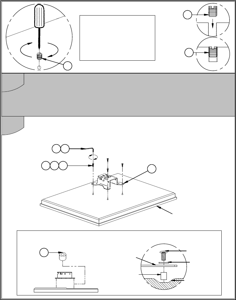
VESA Fixings: 75 x 75mm or 100 x 100mm.
FLAT
SCREEN
RECESS
SPACER
SCREW
INTERFACE
ARM
WASHER
FOR SCREENS WITH RECESS FIXINGS
F
i. Attach interface plate to back of the screen.
T
OP
B
OT
T
O
M
17
C
7
FLAT
SCREEN
16
BA