
Specifications
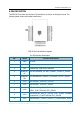
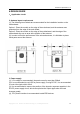
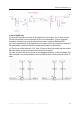
Table Of Contents

ESP32-SL specification V1.0
Copyright © 2019 Shenzhen Ai-Thinker Technology Co., Ltd All Rights Reserved
XIX
OEM/Integrators Installation Manual
Important Notice to OEM integrators
INTEGRATION INSTRUCTIONS
FCC rules
The ESP32-SL is an WIFI+BT Module Module with frequency hopping using an ASK modulation. It
operates on the 2400 ~2500 MHz band and, therefore, is within U.S. FCC part 15.247 standard.
Modular installation instruction
1,ESP32-SL Integrates high-speed GPIO and peripheral interface. Please pay attention to the
installation direction (pin direction).
2,Antenna could not be in no-load state when module is working. During debugging, it is suggested
to add 50 ohms load to the antenna port to avoid damage or performance degradation of the module
under long-time no-load condition.
3,When the module needs to output 31dBm or more power, it needs a voltage supply of 5.0V or
more to achieve the expected output power.
4,When working at full load, it is recommended that the entire bottom surface of the module be
attached to the housing or heat dissipation plate, and it is not recommended to conduct heat
dissipation through air or screw column heat conduction.
5,UART1 and UART2 are serial ports with the same priority. The port which receives commands
returns information.
Trace antenna designs
Not Applicable
RF exposure considerations
To maintain compliance with FCC’s RF Exposure guidelines, This equipment should be installed
and operated with minimum distance between 20cm the radiator your body: Use only the supplied
antenna.
Antennas
The ESP32-SL is an UHF RFID Module beams signals and communicates with its antenna, which is
Panel Antenna.
LABEL OF THE END PRODUCT
The final end product must be labeled in a visible area with the following:
Host must Contains FCC ID: 2ATPO-ESP32-SL. If the size of the end product is larger than
8x10cm, then the following FCC part 15.19 statement has to also be available on the label: This
device complies with Part 15 of FCC rules. Operation is subject to the following two conditions:
(1) this device may not cause harmful interference and
(2) this device must accept any interference received, including interference that may cause
undesired operation.
Information on test modes and additional testing requirements5
Data transfer module demo board can control the EUT work in RF test mode at specified test