
Product Info


B&R wireless board "RFM-2-NF"
Standard Documentation for Radio Equipment Certification
Cable Power Supply – Panel
Copyright © B&R - Subject to modification
Description Module RFM-2-NF_1_Version 1.4.docx
Tuesday, April 9, 2019 2:25:00
PM
5/17
Cable Power Supply – Panel
no
>3m
no
brown: +24V d.c
white: +24V d.c
blue: -24V d.c
black: -24V d.c
grey: PE/FE
Cable PC – Panel (DVI-D)
no
>3m
no
Wiring for PE/FE-connections
(to panel and PC)
no
N/A
no
Wires of the PE/FE-network
should be as short as possi-
ble and must be prepared by
the test house in respect to
the local test environment.
1)
Not all test jigs need the full set of cables as described above. See separate documentation of test jig’s for details.
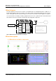
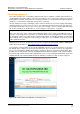
A typical connection of a swing arm variant with SDL4 connection or with DVI-D-Panel link is:
Figure 1: Swing arm version test jig (typical connection scheme)
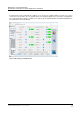
A typical connection of a cabinet version is:
Figure 2: Cabinet version test jig (typical connection scheme)
Remark: Each test jig contains a B&R power supply. If necessary this power supply can be replaced with
a comparable power supply provided by the test house.
Panel (swing arm version)
B&R APC
Cable
Power (24Vd.c)
PE/FE-connection
PE/FE-connection
Power (24Vd.c)
SDL4 or DVI-D
Panel with PPC
PE/FE-connection
Power (24Vd.c)