
User's Manual

31
energy method for duty cycling between active and low power states. Quick start-up from the doze
state, defined in the State Diagram section, allows WSM2400 to wake up and receive data over the
UART and SPI interfaces by simply detecting activity on the appropriate signals.
32.768kHz Crystal Once WSM2400 is powered up and the 32.768kHz crystal source has begun
oscillating, the 32.768kHz crystal remains operational while in the active state, and is used as the timing
basis when in doze state. See the State Diagram section for a description of WSM2400’s operational
states.
20MHZ CRYSTAL
The 20 MHz crystal source provides a frequency reference for the radio, and is automatically enabled
and disabled by WSM2400 as needed.
RADIO
WSM2400 includes the lowest power commercially available 2.4GHz IEEE 802.15.4e radio by a
substantial margin. (Please refer to the Radio Specifications section for power consumption numbers.).
WSM2400’s integrated power amplifier is calibrated and temperature compensated to consistently
provide power at a limit suitable for worldwide radio certifications. Additionally, WSM2400 uniquely
includes a hardware-based autonomous MAC that handles precise sequencing of peripherals, including
the transmitter, the receiver, and Advanced Encryption Standard (AES) peripherals. The hardware-based
autonomous Media Access Controller (MAC) minimizes CPU activity, thereby further decreasing power
consumption.
UARTS
The principal network interface is through the application programming interface (API) UART. A
Command-Line Interface (CLI) is also provided for support of test and debug functions. Both UARTs
sense activity continuously, consuming virtually no power until data is transferred over the port and
then automatically returning to their lowest power state after the conclusion of a transfer.
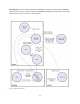
API UART PROTOCOL
The API UART protocol was created with the goal of supporting a wide range of companion Multipoint
Control Units (MCUs) while reducing power consumption of the system. The receive half of the API
UART protocol includes two additional signals in addition to UART_RX: UART_RX_ RTSn and
UART_RX_CTSn. The transmit half of the API UART protocol includes two additional signals in addition
to UART_TX: UART_TX_RTSn and UART_TX_CTSn. The API UART protocol is referred to as Mode 4. In the
Figures accompanying the protocol descriptions, signals driven by the companion processor are drawn
in black and signals driven by WSM2400 are drawn in blue.