
User's Manual

27
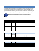
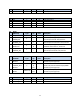
No.
API UART
Type
I/0
PULL
Description
30
UART_RX_RTSn
1 (Note 14)
I
-
UART Receive, Request to Send, Active Low
31
UART_RX_CTSn
1
O
-
UART Receive, Clear to Send, Active Low
32
UART_RX
1 (Note 14)
I
-
UART Receive
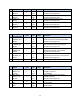
33
UART_TX_RTSn
1
O
-
UART Transmit, Request to Send, Active Low
34
UART_TX_CTSn
1 (Note 14)
I
-
UART Transmit, Clear to Send, Active Low
38
UART_TX
2
O
-
UART Transmit
Note 14: These inputs are always enabled and must be driven or pulled to
a valid state to avoid leakage
Note 15: See also pins 13, 18, and 23 for additional GPIO ports
VSUPPLY: System and I/O Power Supply. Provides power to the module. The digital-interface I/O
voltages are also set by this voltage.
ANTENNA: Multiplexed Receiver Input and Transmitter Output Pin. The impedance presented to the
U.FL connector should be 50Ω, single-ended with respect to ground.
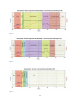
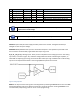
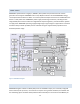
AI_0, AI_1, AI_2, AI_3: Analog Inputs. These pins are multiplexed to the analog input chain. The analog
input chain, as shown in Figure 18, is software-configurable and includes a variable-gain amplifier, an
offset-DAC for adjusting input range, and a 10-bit ADC. Valid input range is between 0V to 1.8V. Analog
inputs can be sampled as described in section Signal/Data Acquisition and Control.
Figure 18. Analog input chain
RESETn: The asynchronous reset signal is internally pulled up. Resetting WSM2400 will result in the ARM
Cortex M3 rebooting and loss of network connectivity. Use of this signal for resetting WSM2400 is not
recommended, except during power-on and in-circuit programming.