
User's Manual

24
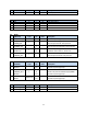
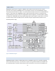
PIN FUNCTIONS
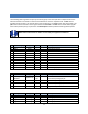
The following table organizes the pins by functional groups. For those I/O with multiple functions the
alternate functions are shown on the second and third line in their respective row. The No column
provides the pin number. The second column lists the function. The Type column lists the I/O type. The
I/O column lists the direction of the signal relative to WSM2400. The Pull column shows which signals
have a fixed passive pull-up or pull-down. The Description column provides a brief signal description.
NOTE: Pin functions shown in italics are currently not supported in software
No.
Power Supply
Type
I/0
PULL
Description
1
GND
Power
-
-
Ground Connection
2
GND
Power
-
-
Ground Connection
3
GND
Power
-
-
Ground Connection
4
GND
Power
-
-
Ground Connection
15
GND
Power
-
-
Ground Connection
28
GND
Power
-
-
Ground Connection
29
GND
Power
-
-
Ground Connection
41
GND
Power
-
-
Ground Connection
53
GND
Power
-
-
Ground Connection
54
GND
Power
-
-
Ground Connection
35
VSUPPLY
Power
-
-
Power Supply Input to WSM2400
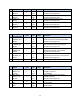
No.
Radio
Type
I/0
PULL
Description
37
RADIO_INHIBIT
GPIO15
1(Note 14)
I
I/O
-
Radio Inhibit
General Purpose Digital I/O
39
GPIO17
1
I/O
-
General Purpose Digital I/O
40
GPIO18
1
I/O
-
General Purpose Digital I/O
42
GPIO19
1
I/O
-
General Purpose Digital I/O
-
Antenna
N/A
N/A
-
Chip Antenna/U.FL Connector
No.
Analog
Type
I/0
PULL
Description
43
AI_0
Analog
I
-
Analog Input 0
44
AI_1
Analog
I
-
Analog Input 1
46
AI_2
Analog
I
-
Analog Input 2
45
AI_3
Analog
I
-
Analog Input 3