
User's Manual

Product Brief – Airborne SDIO/SPI 802.11b/g Radio Quatech, Inc.
846-8310-240 June 2010 5
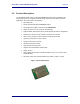
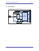
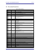
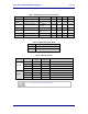
4.0 Pin out and Connectors
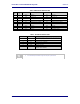
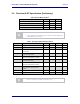
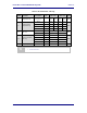
Table 2 – Radio Pin Definition
Pin
Signal
Pin I/O Type
Description
1
GND
Ground
2
GND
Ground
3
DNC
Reserved pin, DO NOT CONNECT
4
VHIO
Supply Input
Host Digital I/O Supply voltage for SDIO/SPI and Bluetooth interfaces.
VHIO = 1.8VDC or VDD. Internally decoupled to GNDHIO.
5
SDIO
Digital Input
Serial Host mode. SPI = GND, SDIO = VDD
6
VHIO
Supply Input
Host Digital I/O Supply voltage for SDIO/SPI and Bluetooth interfaces.
VHIO = 1.8VDC or VDD. Internally decoupled to GNDHIO.
7
DATA2
Digital I/O
SDIO Bit 2 (VHIO Domain)
SDIO 4-bit: Data bit 2 or Read Wait (Optional)
SDIO 1-bit: Read Wait (Optional)
SDIO SPI: Reserved
SPI: SPI Interrupt output (active low)
8
GND
Ground
9
GND
Ground
10
DATA1
Digital I/O
SDIO Bit 1 (VHIO Domain)
SDIO 4-bit: Data bit 1
SDIO 1-bit: Interrupt
SDIO SPI: Reserved
SPI: Data Output
11
DATA3
Digital I/O
SPI/SDIO Card Select (Active Low) (VHIO Domain)
SDIO 4-bit: Data bit 3
SDIO 1-bit: Reserved
SDIO SPI: Card Select (Active Low)
12
SERCLK
Digital Input
SPI/SDIO Clock from host(VHIO Domain)
SDIO 4-bit: Clock input
SDIO 1-bit: Clock Input
SDIO SPI: Clock Input
SPI: Clock Input
13
DATA0
Digital I/O
SDIO Bit 0 (VHIO Domain)
SDIO 4-bit: Data bit 0
SDIO 1-bit: Data Line
SDIO SPI: Data Output
SPI: SPI Device Select (Active Low)
14
CMD
Digital Input
SPI/SDIO data input for 4-Wire mode, data input/output for 3-wire mode. (VHIO Domain)
SDIO Command/Response
SDIO 4-bit: Command/response
SDIO 1-bit: Command
SDIO SPI: 4-wire = Data Input. 3-wire = Data I/O
SPI: Data Input
15
VDD
Analog Supply
Input
Supply Voltage (3.3VDC)
16
WLNAPU
Digital Input
(Pull Down)
Card Power Up Enable from Host (active High). Internal Pull-up.
17
VDD
Analog Supply
Input
Supply Voltage (3.3VDC)
18
SPI_RSTn
Digital Input
SPI Device RESET from MCU. Active Low
19
RF_ACTIVE
Digital Input
Asserted by the BT device during Rx or Tx slots that it wishes to use.
20
DNC
Reserved pin, DO NOT CONNECT
21
TXCONF
Digital Output
Transmission confirmed. Pulled low when the radio wants to prevent the BT device‟s use of the
medium
22
STATUS
Digital Input
Pulsed if the BT device has a priority need for the slot. After that it indicates the BT radio mode (Tx or
RX)
23
DNC
Reserved pin, DO NOT CONNECT
24
MCU_WAKEUP
Digital Output
MCU “wake up” request to the host. Active high. (GPIO5)
25
NC/SLEEPCLK
No connect, optional SLEEPCLK pin for host sourced sleep clock.
26
MAC_WAKEUP
Digital Input
WLAN MAC “wake-up”/interrupt from the host MCU. Active high (GPIO4)
27
UARTSIN
1.8V UART
UART Serial Input.
28
UARTSOUT
1.8V UART
UART Serial Output.
29
GND
Ground
30
GND
Ground