
User's Manual

Product Brief – Airborne SDIO/SPI 802.11b/g Radio Quatech, Inc.
846-8310-240 June 2010 26
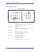
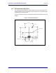
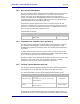
Figure 11 - Recommended Connector Footprint
1.10mm
2.20mm
±0.10mm
30 2
0.25mm
±0.05mm
29
0.50mm
±0.05mm
1.80mm
±0.10mm
1
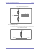
11.6 Mechanical Mounting
It is recommended that mechanical mounting, other than the mated connector,
be used to secure the radio to the host system. The radio includes four (4) holes
specifically for this purpose. These holes are provides in the four corners and are
unplated, this allows the use of metallic mounting systems without impacting the
electrical performance of the unit.
The mounting holes can be seen in Fig, they are 1.85mm in diameter. A
mechanical spacer will be required to maintain the physical separation of the
board from the host and aid in ensuring optimal interference in the connector.
The height of the spacer should be 3mm±0.1mm. The material should not be
easily compressed.
11.7 EMI/EMF Guidelines
To minimize electromagnetic interference (EMI) and radio frequency interference
(RFI), pay strict attention to power and signal routing near the Radio. As much as
possible, the keep-clear area below the Radio should be a solid copper ground
plane. It is anticipated that the Radio will be mounted on a board with a
committed ground plane. Ensure the PCB interconnect has a designed
impedance of 50-75 Ohms.
To keep signal impedance as low as possible, connect the ground plane to
internal ground planes by several vias. Ground signals to the Radio connector
should connect directly to the ground plane below the Radio. Individual ground
connections to the Radio should have a solid ground connection, preferably
directly to the ground plane on the same surface side where the Radio resides.
Do not connect ground pins directly to an inside layer ground plane using vias
only.