Product Specification 802.11b/g SDIO/SPI Airborne Radio WLRG-RA-DP600 Family Revision: 2.4 June 2010 File name: wlrg-ra-dp601 product brief v2.
Product Brief – Airborne SDIO/SPI 802.11b/g Radio 1.0 Quatech, Inc. Product Description The WLNG-RA-DP600 family is a Marvell 88W8686 based 802.11b/g SDIO/SPI radio, designed by Quatech, to support handheld, mobile station and other power sensitive applications. The radio features the following: 802.11b/g radio Based upon Marvell Libertas 88W8686 Chipset 30 pin high density SMT connector (Molex 53748-0308) Single (1) Hirose U.FL RF connector for 802.
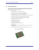
Product Brief – Airborne SDIO/SPI 802.11b/g Radio 2.0 Quatech, Inc. Block Diagram The following outlines the block diagram of the radio: VDD (3.3VDC) Power Management 802.11b/g RF Serial EEPROM Marvell 88W8686 IEEE 802.11 MAC Processor & RF Transciever 802.11b/g FEM BT Coexistence U.FL RF Connector SDIO/SPI Interface VHIO (1.8VDC or VDD) External Sleep Clock Option Available 40 MHz Xtal Oscillator 846-8310-240 32.
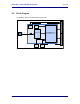
Product Brief – Airborne SDIO/SPI 802.11b/g Radio 3.0 Quatech, Inc. Model Numbers The following table identifies the model numbers associated with the radio family. Please contact Quatech sales for details, quotes and availability. Table 1 - Model Numbers WiFi Model Number WLRG-RA-DP601 Interface Supply Description RoHS 802.11b 802.11g SDIO SPI BT Co VDD VHIO l l l1 l1 l l l 802.11b/g, SDIO/SPI, Bluetooth Coexistence, VDD & VHIO supply (Lakemore) l Eval Kit 802.
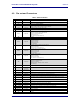
Product Brief – Airborne SDIO/SPI 802.11b/g Radio 4.0 Quatech, Inc. Pin out and Connectors Table 2 – Radio Pin Definition Pin Signal 1 GND Pin I/O Type Description Ground 2 GND Ground 3 DNC 4 VHIO Supply Input Host Digital I/O Supply voltage for SDIO/SPI and Bluetooth interfaces. VHIO = 1.8VDC or VDD. Internally decoupled to GNDHIO. 5 SDIO Digital Input Serial Host mode. SPI = GND, SDIO = VDD 6 VHIO Supply Input Host Digital I/O Supply voltage for SDIO/SPI and Bluetooth interfaces.
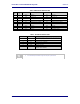
Product Brief – Airborne SDIO/SPI 802.11b/g Radio Quatech, Inc. Table 3 - SDIO Interface Definition Table SDIO Pin Module Pin SD 4-bit Pin Name 1 11 DATA3 Data bit 3 N/C Reserved 2 14 CMD Command line. CMD Command line.
Product Brief – Airborne SDIO/SPI 802.11b/g Radio Quatech, Inc. There are a total of two connectors to the radio: J1: 30 pin Digital SDIO/SPI Host interface to radio Baseband processor. Molex: 0537480308 (0.50mm (.020") Pitch SlimStack™Plug, Surface Mount, Dual Row, Vertical, 3.00mm (.118") Stack Height, 30 Circuits) J2: RF connector for 802.11b/g antenna. Hirose U.FL.
Product Brief – Airborne SDIO/SPI 802.11b/g Radio 5.0 Quatech, Inc. Electrical & RF Specification (Preliminary) Table 5- Absolute Maximum Values1 Parameter Min Max Unit Maximum EMU Supply Voltage -0.3 7.0 VDC Power Dissipation Operating Temperature Range 2.00 2 Storage Temperature W -30 85 o -50 125 o C C 1. These are absolute ratings; exceeding these values may cause permanent damage to the device. 2.
Product Brief – Airborne SDIO/SPI 802.11b/g Radio Quatech, Inc. Table 7 - SDIO/SPI Interface Electrical Characteristics Symbol Parameter Min Typ Max Units VIHSDIO Input HIGH Voltage VCC=MAX, MIN VILSDIO Input LOW voltage VCC=MIN, MAX 0.7 VHIO VHIO+0.3 V 0 0.3 VHIO V VOHSDIO Output HIGH Voltage IOL = 0.2mA, VCC=MIN VHIO-0.2 VHIO V VOLSDIO Output LOW voltage IOL = 6mA, VCC=MIN 0 0.
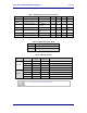
Product Brief – Airborne SDIO/SPI 802.11b/g Radio Quatech, Inc. Table 10 - RF Characteristics – 802.11b/g Peak dBm / mW Parameter Rate (Mbps) POUTB Transmit Power Output 802.11b 11, 5.5, 2, 1 13.2 20.1 18.2 66.1 48, 54 12.8 19.1 17.3 53.7 24, 36 12.7 18.6 17.2 52.5 12, 18 12.8 19.1 17.3 53.7 6, 9 12.5 17.8 17.0 50.1 POUTG PRSENB PRSENG FRANGEBG 846-8310-240 Transmit Power Output 802.11g Receive Sensitivity 802.11b Receive Sensitivity 802.
Product Brief – Airborne SDIO/SPI 802.11b/g Radio 6.0 Quatech, Inc. Antenna The unit supports antenna connection through a single Hirose U.FL connector, located on the top surface of the radio next to the RF shielding. Any antenna used with the system must be designed for operation within the 2.4GHz ISM band and specifically must support the 2.412GHz to 2.482GHz for 802.11b/g operation. They are required to have a VSWR of 2:1 maximum referenced to a 50 system impedance. 6.
Product Brief – Airborne SDIO/SPI 802.11b/g Radio Quatech, Inc. TNC/SMA are not allowed (there are more that are not), RP-TNC/RP-SMA are allowed. 6.3 Host Chassis Mounted Antenna Host Chassis mounted antennas require no work on the host PCB. They utilize an antenna type called „flying lead‟. There are two types of flying leads; one which provides a bulkhead mounted antenna connector and one which provides a bulk head mounted antenna. The type you choose will be determined by the application.
Product Brief – Airborne SDIO/SPI 802.11b/g Radio Quatech, Inc. PCB Embedded – This approach embeds an antenna design into the host PCB. This approach is very common with add-in WiFi card (CF, PCMCIA, SDIO, etc.) as it requires no external connections and is the cheapest production approach. The lower production cost requires significant development cost and lack of performance and flexibility.
Product Brief – Airborne SDIO/SPI 802.11b/g Radio Quatech, Inc. Locate the antenna where there is a minimum of obstruction between the antenna and the location of the Access Points. Typically Access Points are located in the ceiling or high on walls. Keep the main antenna‟s polarization vertical, or in-line with the antenna of the Access Points. 802.11 systems utilize vertical polarization and aligning both transmit and receive antenna maximizes the link quality.
Product Brief – Airborne SDIO/SPI 802.11b/g Radio Quatech, Inc.
Product Brief – Airborne SDIO/SPI 802.11b/g Radio 7.0 Quatech, Inc. Bluetooth Coexistence Interface The Bluetooth coexistence interface implemented on the Airborne 802.11b/g WLRG-RADP600 family of radio‟s is a three wire configuration, designed to support the identified coexistence recommended practices in the IEEE 802.15.2 standard for the coexistence of WLAN and Bluetooth devices. This includes collaborative TDMA method described as Packet Traffic Arbitration (PTA).
Product Brief – Airborne SDIO/SPI 802.11b/g Radio 8.0 Quatech, Inc. GSPI Interface The General Serial Peripheral Interface (GSPI) for the WLRG-RA-DP601 is detailed in the following section. The interface is powered by the VHIO (pin 4 & 6) supply as defined in Table 2. 8.1 SPI Protocol Timing The following figures and table define the required timing for the GSPI interface.
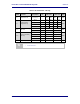
Product Brief – Airborne SDIO/SPI 802.11b/g Radio Quatech, Inc. Table 13 - GSPI Protocol Timing Values 846-8310-240 Symbol Parameter Min TSCLK Clock period 20 ns TWH Clock High 5 ns TWL Clock Low 9 ns TWR Clock Rise Time 1 ns TWF Clock Fall Time 1 ns TH Serial Data In Hold Time 2.5 ns TSU Serial Data In Setup Time 2.
Product Brief – Airborne SDIO/SPI 802.11b/g Radio 9.0 Quatech, Inc. SDIO Interface The Serial Data Input Output (SDIO) interface for the WLRG-RA-DP601 is detailed in the following section. The interface is powered by the VHIO (pin 4 & 6) supply as defined in Table 2. The interface is compliant to v1.0 of the SDIO interface standard. 9.1 SDIO Protocol Timing The following figures and table define the required timing for the SDIO interface.
Product Brief – Airborne SDIO/SPI 802.11b/g Radio Quatech, Inc.
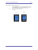
Product Brief – Airborne SDIO/SPI 802.11b/g Radio Quatech, Inc. 10.0 Mechanical Outline Figure 6 - Mechanical Outline 21.00mm 0.80mm 4.50mm Ø1.85mm 802.11 Antenna Connector 12.00mm 25.00mm 29.00mm 12.50mm Molex 53748-0308 1 29 2 30 8.50mm 1.20mm 2.50mm 5.87mm 17.00mm BOTTOM VIEW Radio Connector: TOP VIEW 0537480308 (Molex) (0.50mm (.020") Pitch SlimStack™ Plug, Surface Mount, Dual Row, Vertical, 3.00mm (.118") Stack Height, 30 Circuits) Board Connector: 0529910308 (0.50mm (.
Product Brief – Airborne SDIO/SPI 802.11b/g Radio Quatech, Inc. 11.0 Design Guidelines The WLRG-RA-DP601 is designed for integration in to a wide range of advanced electronic systems and diverse applications, the success of the integration and final performance of the complete system depends upon the integration process and hardware design, the following section provides a set of guidelines to aid in the integration of the radio.
Product Brief – Airborne SDIO/SPI 802.11b/g Radio Quatech, Inc. Figure 7 - SDIO (Pin #5) Configuration Options 100K VDD R1 SDIO SPI 0 SDIO 11.3 R1 ü DNP R2 DNP ü R2 WLNAPU (pin #16) This pin should be pulled to VHIO through a 100K resistor, as shown in Fig XX.
Product Brief – Airborne SDIO/SPI 802.11b/g Radio 11.4 Quatech, Inc. SPI_RSTn (pin #18) This pin should be pulled to VHIO through a 100K resistor, as shown in Figure 9.
Product Brief – Airborne SDIO/SPI 802.11b/g Radio 11.5 Quatech, Inc. Recommended PCB Layout The following outlines Quatech‟s recommendations for layout of the PCB for the WLRG-RA-DP601, these are guidelines only and should serve as guidance when designing the host system board. If there are questions relating to the guidelines please contact Quatech Technical Support. Figure 10 - Recommended PCB Layout 21.00mm Ø1.85mm Board Outline 25.00mm 29.00mm 12.50mm Molex 52991-0308 29 1 30 2 8.50mm 1.
Product Brief – Airborne SDIO/SPI 802.11b/g Radio Quatech, Inc. Figure 11 - Recommended Connector Footprint 0.25mm±0.05mm 0.50mm±0.05mm 29 1 1.80mm±0.10mm 1.10mm 2.20mm±0.10mm 30 11.6 2 Mechanical Mounting It is recommended that mechanical mounting, other than the mated connector, be used to secure the radio to the host system. The radio includes four (4) holes specifically for this purpose.
Product Brief – Airborne SDIO/SPI 802.11b/g Radio Quatech, Inc. Keep interconnects from the Radio connector as short as possible on the mounting layer. All inboard signals–including pin numbers–must immediately transition to a different routing layer using a via as close to the connector as possible. Outboard signals (odd pin numbers) should also be kept to a minimum length.
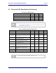
Product Brief – Airborne SDIO/SPI 802.11b/g Radio Quatech, Inc. 12.0 Certification & Regulatory Approvals The unit complies with the following agency approvals: Table 16 - Regulatory Approvals Country Standard North America (US & Canada) Status FCC Part 15, Sec. 15.107, 15.109, 15.207, 15.209, 15.247 Granted RSS-210 Modular Approval EN60950 inc. A1, A2, A3, A4 ETSI EN 300 328 Part 1 V1.2.2 (2000-07) ETSI EN 300 328 Part 2 V1.1.1 (2000-07) Europe Pending ETSI EN 301 893 V1.2.
Product Brief – Airborne SDIO/SPI 802.11b/g Radio 12.3 Quatech, Inc. RF Exposure Information The radio module has been evaluated under FCC Bulletin OET 65C (01-01) and found to be compliant to the requirements as set forth in CFR 47 Sections, 2.1093, and 15.247 (b) (4) addressing RF Exposure from radio frequency devices. This model meets the applicable government requirements for exposure to radio frequency waves. The highest SAR level measured for this device was 0.993 W/kg (802.11b) and 0.
Product Brief – Airborne SDIO/SPI 802.11b/g Radio Quatech, Inc. Radiator testing and certification, except where they wish to use an antenna that is not already certified. Quatech supports a group of pre-approved antenna; use of one of these antennas eliminates the need to do any further subpart C testing or certification. If an antenna is not on the list, it is a simple process to add it to the pre-approved list without having to complete a full set of emissions testing.
Product Brief – Airborne SDIO/SPI 802.11b/g Radio Quatech, Inc. 13.0 Change Log The following table indicates all changes made to this document: Version Date Section A 2/11/2007 - B 2/19/2007 4.0 1.3 3/12/2008 Change Description Author Internal Release ACR Updated Table 2.0 ACR - Changed revision numbering from Alpha to Numeric ACR 2.0 Updated block diagram to remove BT RF connector. 4.0 Updated Table 2.0 to reflect updated pin out.