
User Manual

B&B Electronics, Inc. Airborne WLNN DP550 Family Databook
4
Figures
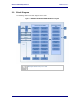
Figure 1 – APMN-Q551/WLNN-SE/SP/AN/ER-DP550 Block Diagram ............................................... 7
Figure 2 - SPI Read/Write Timing ............................................................................................................20
Figure 3 - SPI Clock and Select Timing ..................................................................................................20
Figure 4 - Power on RESET Timing .........................................................................................................29
Figure 5 - RESET Timing ..........................................................................................................................29
Figure 6 – DP550 Mechanical Outline .....................................................................................................30
Figure 7 - Recommended PCB Footprint ................................................................................................31
Figure 8 - Full FCC/IC Label .....................................................................................................................36
Figure 9 - Minimum FCC/IC Label ...........................................................................................................36
Tables
Table 1 - Model Numbers ........................................................................................................................... 8
Table 2 – Module Pin Definition ................................................................................................................. 9
Table 3 - UART Pin Definition ...................................................................................................................11
Table 4- Absolute Maximum Values
1
.......................................................................................................14
Table 5 – Operating Conditions & DC Specification ..............................................................................14
Table 6 - RF Characteristics – 802.11a/b/g/n .........................................................................................16
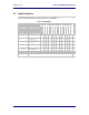
Table 7 - Supported Data Rates by Band ...............................................................................................17
Table 8 - Operating Channels ...................................................................................................................17
Table 9 - Radio Typical Performance Range .........................................................................................18
Table 10 - SPI Pinout Details ....................................................................................................................19
Table 11 - SPI Signal Descriptions ..........................................................................................................19
Table 12 - SPI AC Timings ........................................................................................................................20
Table 13 - TX Message Header ...............................................................................................................21
Table 14 - RX Message Header ...............................................................................................................21
Table 15 - SPI Modes ................................................................................................................................22
Table 16 - SPI Command Description .....................................................................................................22
Table 17 - Embedded Antenna Options ..................................................................................................26
Table 18 - RESET Timing ..........................................................................................................................29
Table 19 - Regulatory Approvals ..............................................................................................................32
Table 20 - Modular Grant Numbers .........................................................................................................35
Table 21 - Mechanical Approvals .............................................................................................................37