
User's Manual

Company Confidential Quatech, Inc.
28 100-8026-100G Airborne 802.11b/g Value Radio Databook Revision 1.0
11.0 Integration Guidelines
The Airborne Performance Radio is designed for integration in to a wide range of
advanced electronic systems and diverse applications, the success of the integration and
final performance of the integrated system depends upon the integration process and
hardware design, the following section provides a set of guidelines to optimize the
integration of the radio.
The following guidelines address hardware design requirements for the integration of the
radio under normal conditions, should your application not be able to support the listed
guidelines please contact Quatech.
11.1 General Requirements
3.3VDC65% on all V
DD
pins
Digital Ground on all V
SS
pins
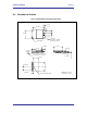
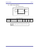
Mechanical mounting method other than J1
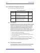
11.2 Power Supply Guidelines
3.3VDC65%
500mA constant current
3000mA start-up current for 35ms
150mV ripple voltage (f<50Hz) at constant receive current
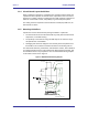
11.3 EMI/EMF Guidelines
To minimize electromagnetic interference (EMI) and radio frequency interference
(RFI), pay strict attention to power and signal routing near the Radio. As much as
possible, the keep-clear area below the Radio should be a solid copper ground
plane. It is anticipated that the Radio will be mounted on a board with a
committed ground plane. Ensure the PCB interconnect has a designed
impedance of 50-75 Ohms.
To keep signal impedance as low as possible, connect the ground plane to
internal ground planes by several vias. Ground signals to the Radio connector
should connect directly to the ground plane below the Radio. Individual ground
connections to the Radio should have a solid ground connection, preferably
directly to the ground plane on the same surface side where the Radio resides.
Do not connect ground pins directly to an inside layer ground plane using vias
only.
Keep interconnects from the Radio connector as short as possible on the
mounting layer. All inboard signals–including pin numbers–must immediately
transition to a different routing layer using a via as close to the connector as
possible. Outboard signals (odd pin numbers) should also be kept to a minimum
length.