
User's Manual
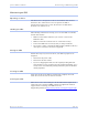
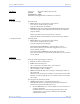
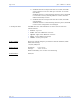
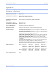
Table Of Contents
- T
- Table of contents
- I
- Introduction
- M
- Making connections
- E
- Enabling Wi-Fi Device Servers
- Installing the device drivers
- C
- Configuring the SDS using the Web interface
- T
- Troubleshooting and Maintaining an SDS
- Appendix A
- Appendix B
- Appendix C

Quate c h SDS Us e r’s Manual Appe ndix A
Re v 1 .5 0 (3 /1 3/2 00 5 ) Page 81
Signals:
RJ-45:
DB-9:
View looking into
the connector
View looking into
the connector
RS-232
signal
Pin # RS-422/ 485 signal,
4-wire m ode
RS-422/ 485 signal,
2-wire m ode
RI 1
TxD– Transmit/Receive Data (Data–)
RTS 2
AuxOut+
N/C
DTR 3
AuxOut–
N/C
GND 4
GND Signal Ground (GND)
TxD 5
TxD+ Transmit/Receive Data (Data+)
RxD 6
RxD+
N/C
DCD 7
AuxIn–
N/C
DSR 8
RxD–
N/C
CTS 9
AuxIn+
N/C
N/C 10
N/C N/C
RS-232
signal
Pin # RS-422/ 485 signal,
4-wire m ode
RS-422/ 485 signal,
2-wire m ode
DCD 1 AuxIn–
N/C
RxD 2 RxD+
N/C
TxD 3 TxD+
Transmit/Receive Data (Data+)
DTR 4 AuxOut–
N/C
GND 5 GND
Signal Ground (GND)
DSR 6 RxD–
N/C
RTS 7 AuxOut+
N/C
CTS 8 AuxIn+
N/C
RI 9 TxD–
Transmit/Receive Data (Data–)