
User's Manual
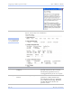
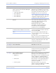
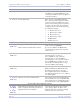
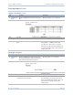
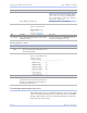
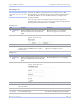
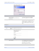
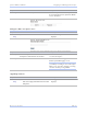
Table Of Contents
- T
- Table of contents
- I
- Introduction
- M
- Making connections
- E
- Enabling Wi-Fi Device Servers
- Installing the device drivers
- C
- Configuring the SDS using the Web interface
- T
- Troubleshooting and Maintaining an SDS
- Appendix A
- Appendix B
- Appendix C

Configuring the SDS using a We b inte rface Quate ch SDS Use r’s Manual
Page 68 Re v 1 .5 0 (3/1 3 /20 0 5)
Step Procedure Description
# Step 3j Set the UDP port designation. Enter a valid UDP port number to which
the SDS can send. The SDS will receive
on both port 5000 and on the designated
serial port number.
# Step 3k
Set the TTL value. This selection sets the TTL (Time To
Live) value for multicast packets. Each
router decrements the TTL value of the
packet and will only forward a packet if
its value is greater than the threshold
configured on the router. The following
are standard settings:
! 0 Restricted to host
! 1 Restricted to subnet
! 15 Restricted to site
! 63 Restricted to region
! 127 Worldwide
! 255 Unrestricted
Steps 4a through 4d apply only to RS-232/ 422/ 485 (MEI) units
# Step 4a
(MEI only)
Configure the serial port interface.
Click on the desired interface selector.
This series of steps only applies to MEI
units, such as the SSE-400.
If you select RS232, the RS422/485
selections will be grayed out. Continue
with
□ Step 5.
# Step 4b
(MEI only)
Click on the desired duplex mode selector. Select Full Duplex to always enable
transmit and receive drivers.
Select Half Rx to only enable the
transmit drivers when the SDS is
transmitting; receivers always enabled.
Select Half Rx Tog to disable receivers
and enable the transmit drivers only
when the SDS is transmitting.
# Step 4c
(MEI only)
Click on the desired connector setup. Select Loopback All to internally loopback
RTS and CTS in the SDS. AuxIn and
AuxOut are looped at the connector.
Select Modem Control to send RTS on
the AuxOut signal and to receive CTS on
the AuxIn signal.
# Step 4d
(MEI only)
Select 2- or 4-wire communication. Select 2-wire to use the transmit pair for
both transmit and receive in RS-422/485.
Select 4-wire to use a separate pair of wires
for transmit and receive in RS-422/485.
Step 4 (non-MEI) / Step 5 (MEI) applies to all units
# Step 4
(non-MEI)
or
# Step 5
(MEI only)
Repeat the steps above for each port you
need to configure and then press Save to
implement all of your changes.
Close and re-open the port to activate
your changes. That’s it! You’re done.
Normal is the most common operating
mode and the easiest to set up.