
User's Manual
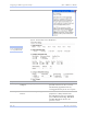
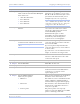
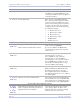
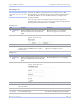
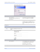
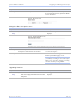
Table Of Contents
- T
- Table of contents
- I
- Introduction
- M
- Making connections
- E
- Enabling Wi-Fi Device Servers
- Installing the device drivers
- C
- Configuring the SDS using the Web interface
- T
- Troubleshooting and Maintaining an SDS
- Appendix A
- Appendix B
- Appendix C

Quate c h SDS Us e r’s Manual Configuring the SDS using a We b inte rface
Re v 1 .5 0 (3 /1 3/2 00 5 ) Page 67
Step Procedure Description
# Step 3a Configure the Operating mode.
Click on the desired data Rate Multiplier.
Your choices are:
! Auto (Recommended)
! Force X2 mode
! Force X4 mode
! Force X8 mode
The auto setting has no effect on the
baud rate you set. However, if you select
X2, X4, or X8, the baud rate of the serial
port will be the baud rate that you set
multiplied by 2, 4, or 8, respectively.
Note: Forcing a change in the data rate may
cause communication problems with some
serial devices. If this is the case, change the
setting back to Auto (Recommended).
# Step 3b Click on the desired Performance
Selector.
Choose balanced mode except in those
cases where the serial device cannot
tolerate the slight delays inherent in
normal TCP/IP operation.
Balanced mode offers excellent
performance for most applications.
Low Latency mode heavily favors
responsiveness over throughput.
# Step 3c Set the Heart Beat Time to a value from 1
to 65534 seconds. Default is 45 seconds.
Note: Use a value of 0 to disable the heartbeat
timer.
Heartbeat messages help detect when a
connection has been lost between the PC
driver and the SDS.
If you need quick notification that the
connection has been lost, set this timer to
a shorter value.
If you are more concerned about network
traffic, set this timer to a longer value.
# Step 3d Set the Baud Rate. The SDS and the serial device(s) to
which it is attached must use the same
serial connection speed.
# Step 3e Set the Parity. Parity can be odd, even, or none.
# Step 3f Set the Data Bits. Data Bits can be 7 or 8.
# Step 3g Set the Stop Bits. Stop Bits can be 1 or 2.
# Step 3h Set the Flow Control. Flow control determines the handshake
method used between the SDS and the
serial device(s) to stop the serial
input/output process
# Step 3i Set the UDP/IP Address.
These are your options:
! Multicast
! Broadcast
! Point to point
This selection determines the destination
IP address where data will be sent.
For multicast, enter a valid multicast IP
address (244.0.0.0 – 239.255.255.255) to
broadcast data to a specific multicast group.
For broadcast, enter 255.255.255.255 to
broadcast the serial data to all devices
ready to accept data.
For point to point, enter a specific
address to which the SDS can send UDP
packets containing serial data.