
User's Manual
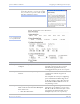
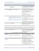
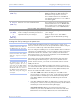
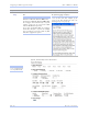
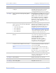
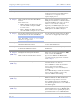
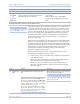
Table Of Contents
- T
- Table of contents
- I
- Introduction
- M
- Making connections
- E
- Enabling Wi-Fi Device Servers
- Installing the device drivers
- C
- Configuring the SDS using the Web interface
- T
- Troubleshooting and Maintaining an SDS
- Appendix A
- Appendix B
- Appendix C

Configuring the SDS using a We b inte rface Quate ch SDS Use r’s Manual
Page 64 Re v 1 .5 0 (3/1 3 /20 0 5)
Step Procedure Description
# Step 3h Set the Flow Control. Flow control determines the handshake
method used between the SDS and the
serial device(s) to stop the serial
input/output process
# Step 3i
Click on the desired Auto TCP Mode
selector.
Your choices are:
! DSR – Initiate the TCP connection
when the SDS serial port’s DSR
becomes active
! Data – Initiate the TCP connection
when the SDS serial port receives data
This selection determines whether the
SDS port will initiate a communications
link when DSR becomes active or when
data is received at the serial port.
Typically, the DTR output of the device
to which you are connecting drives the
DSR input on the SDS serial port.
# Step 3j
Set the Auto TCP timeout interval if you
selected Data as the Auto TCP Mode.
Note: This selection is only available if the
Auto TCP Mode selector is set to Data.
Otherwise, it is grayed out.
Sets the amount of time before the TCP
connection is dropped after data stops.
# Step 3k
Set the IP Address of the TCP host to
which the SDS will connect.
This selection sets the IP address to be
used in Auto TCP mode.
# Step 3l Set the TCP Port number of the TCP host
to which the SDS will connect.
This selection sets the TCP port for Auto
TCP modes.
Steps 4a through 4d apply only to RS-232/ 422/ 485 (MEI) units
# Step 4a
(MEI only)
Configure the serial port interface.
Click on the desired interface selector.
This series of steps only applies to MEI
units, such as the SSE-400.
If you select RS232, the RS422/485
selections will be grayed out. Continue
with
□ Step 5.
# Step 4b
(MEI only)
Click on the desired duplex mode selector. Select Full Duplex to always enable
transmit and receive drivers.
Select Half Rx to enable the transmit
drivers only when the SDS is
transmitting; receivers will always be
enabled.
Select Half Rx Tog to enable the transmit
drivers and to disable receivers only
when the SDS is transmitting.
# Step 4c
(MEI only)
Click on the desired connector setup. Select Loopback All to internally loopback
RTS and CTS in the SDS. AuxIn and
AuxOut are looped at the connector.
Select Modem Control to send RTS on
the AuxOut signal and to receive CTS on
the AuxIn signal.
# Step 4d
(MEI only)
Select 2- or 4-wire communication. Select 2-wire to use the transmit pair for
both transmit and receive in RS-422/485.
Select 4-wire to use a separate pair of wires
for transmit and receive in RS-422/485.