
User's Manual
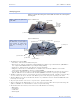
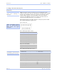
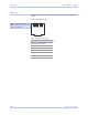
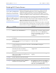
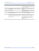
Table Of Contents
- T
- Table of contents
- I
- Introduction
- M
- Making connections
- E
- Enabling Wi-Fi Device Servers
- Installing the device drivers
- C
- Configuring the SDS using the Web interface
- T
- Troubleshooting and Maintaining an SDS
- Appendix A
- Appendix B
- Appendix C

Intro ductio n Quate c h SDS Use r’s Manual
Page 12 Re v 1 .5 0 (3/1 3 /20 0 5)
Network port
All SDS devices have one eight-pin RJ-45 Ethernet port on the back
panel.
Figure 5 - RJ-45 Ethernet port pinout
1 2 3 4 5 6 7 8
Table 7 - RJ-45 Ethernet port signals
Ethernet signal description RJ-45
Transmit Data (TxD+) 1
Transmit Data (TxD–) 2
Receive Data (RxD+) 3
No connection 4, 5
Receive Data (RxD–) 6
No connection 7, 8
Figure 5 and Table 7 show the
Ethernet RJ-45 pinouts and
signal descriptions.