
User's Manual
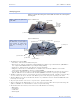
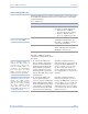
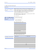
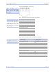
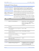
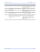
Table Of Contents
- T
- Table of contents
- I
- Introduction
- M
- Making connections
- E
- Enabling Wi-Fi Device Servers
- Installing the device drivers
- C
- Configuring the SDS using the Web interface
- T
- Troubleshooting and Maintaining an SDS
- Appendix A
- Appendix B
- Appendix C

Intro ductio n Quate c h SDS Use r’s Manual
Page 8 Re v 1 .5 0 (3/1 3 /20 0 5)
Identifying parts
Figures 1 and 2 show the parts of the SDS. See below for a description
of each part.
Figure 1 - SDS front view
Figure 2 - SDS back view
Figure 1 shows the front view
of the SDS.
1 . The SDS has five indicator LEDs:
! Po we r (blue ) – indicates whe n the SDS has line po we r
! Data (re d/ gre en) – indic ates serial po rt data activity by blinking red fo r RS-2 3 2 o r gre e n fo r RS-4 2 2 / 4 8 5 ; QSE-/ ESE-1 0 0 s
have a single re d Data LED that indicates any serial po rt ac tivity by blinking
! Status (green) – indicates whe n the e mbedde d pro cesso r is up and running
! Link (gree n) – indicates whe n a network link has be en e stablishe d; locate d o n left side of Etherne t conne ctor in RS-
2 3 2 / 4 2 2 / 4 8 5 units; QSE-/ ESE-1 0 0 s also have a separate Link LED
! Spe e d (ambe r) – diffe re ntiate s betwee n 1 0 0 Base -T (glowing) and 1 0 Base -T (o ff) Ethe rne t c o nne c tio n spe e ds; locate d o n
right side o f Ethe rnet co nnector in RS-2 3 2 / 4 2 2 / 4 8 5 units; QSE/ ESE-1 0 0 s also have a se parate gre e n Spe e d LED
2 . The DB-9 s e rial po rt(s) conne ct to yo ur serial de vice(s) and can suppo rt RS-2 3 2 , RS-4 2 2 , or RS-4 8 5 c o nnections . They
are lo c ated e ithe r to the left, to e ithe r side o f the Ethe rne t po rt, o r o n the fro nt pane l, depe nding on the mo de l.
3 . The RJ-45 Etherne t po rt co nne cts the SDS to the Inte rnet o r to your Intrane t. It has two small status LEDs: Link on the
le ft and Spe e d o n the right.
4 . The po we r jac k sho uld be c o nnected to a +5 V po we r sourc e , provided with the SDS.
5 . The Re se t button puts the SDS through a re set cyc le and can also re store the SDS to the fac to ry default se ttings. The
QSE-1 0 0 and ESE-10 0 us e a Default button to re store fac tory default se ttings.
6 . The info rmation labe l (no t sho wn) is o n the botto m o f the SDS. It includes the fo llo wing:
! MAC address
! Se rial number
! Certifications
! Pinout diagram
(4) Power jack
(2) Serial ports
(1) Status LED
(5) Reset button
(3) Ethernet port
(4) Power jack
Figure 2 shows the rear view of
the SDS. The actual number
and location of serial ports
will vary according to the
model.
(2) Serial ports
(1) Power LED
(1)
Link LED
Speed LED
(3) Ethernet port
(1) Data LEDs
(1)
Power LED
Link LED
Speed LED
Data LED
(5) Default button
(5) Reset button
(1) Status LED