CON N ECT W ITH RELIA B ILITY Serial Device Server User’s Manual QUATECH, INC. 5 6 7 5 Hudso n Industrial Parkway Hudso n, Ohio 4 4 2 3 6 -5 0 1 2 To ll fre e : 1 -8 0 0 -5 5 3 -1 1 7 0 http:/ / www.quate c h.
Copyright Copyright © 2005 Quatech, Inc. All rights are reserved. The information contained in this document cannot be reproduced in any form without the written consent of Quatech, Inc. Any software programs that might accompany this document can be used only in accordance with any license agreement(s) between the purchaser and Quatech, Inc. Quatech, Inc. reserves the right to change this documentation or the product to which it refers at any time and without notice.
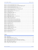
Quate c h SDS Use r’s Manual Table o f c o nte nts Table of contents Introduction ----------------------------------------------------------------------------------------------------------------------- 1 Understanding how virtual communication ports work-------------------------------------------------------- 2 Understanding MAC and IP addresses and port numbers----------------------------------------------- 2 Identifying operating modes---------------------------------------------------------------------
Table o f c o nte nts Quate c h SDS Use r’s Manual Troubleshooting and Maintaining an SDS------------------------------------------------------------------------------76 Troubleshooting an SDS ------------------------------------------------------------------------------------------------76 Maintaining an SDS -----------------------------------------------------------------------------------------------------79 Operating conditions --------------------------------------------------------------------------
Quate c h SDS Use r’s Manual Table o f c o nte nts Figure 34 - Locate the Serial Device Server screen................................................................................. 36 Figure 35 - Locate the Serial Device Server using direct discovery screen ........................................... 37 Figure 36 - Locate the Serial Device Server on a remote subnet screen ............................................... 38 Figure 37 - Describe the Remote Subnet screen.....................................
Quate c h SDS Use r’s Manual Intro duc tio n Introduction Quatech’s line of Serial Device Servers (SDS) is designed to networkenable any device currently using RS-232 or RS-422/485 serial communications protocols. Our Device Servers provide industryleading hardware and user-friendly software to make connecting your serial devices to an Ethernet network a surprisingly simple process.
Intro duc tio n Quate c h SDS Use r’s Manual Understanding how virtual com m unication ports work Note: Quatech Device Server technology now allows access to individual serial devices by anyone with access to the network on which they are installed. Note: Anyone in your organization with a PC can connect to the serial device over the network just as though the two devices were directly connected.
Quate c h SDS Use r’s Manual Intro duc tio n Using Port num bers Note: You can think of the IP address as a telephone number and the port number as a telephone extension. Note: This information is useful for firewall configuration. In order for devices to communicate via a TCP connection or a UDP datagram, they must know each other’s IP address and port number. The SDS driver automatically sets the unit’s port number for you. A specific port number identifies each SDS serial port.
Intro duc tio n Quate c h SDS Use r’s Manual IP address and TCP port number of the network host to which it should connect. If the SDS is idle, it will listen for normal Raw TCP mode connections from the network host. Raw UDP m ode Note: Raw UDP can provide one-to-many communications. Raw UDP is used primarily for broadcasting messages over a network. It is lightweight and efficient; however, your application program must handle all error processing and retransmission.
Quate c h SDS Use r’s Manual Intro duc tio n Features Note: Quatech Device Servers capture data from legacy serial devices without having to go through a PC. Quatech Device Servers can connect virtually any serial device to any standard Ethernet network (Intranet or Internet) using TCP/IP protocols.
Intro duc tio n Note: Traps are messages or alarms generated by an SNMP agent to indicate to the SNMP manager that a significant event has occurred. Quate c h SDS Use r’s Manual information that a management network host can retrieve using the Get command. In addition to providing information upon request, the SDS supports a cold start Trap, which is a spontaneous message the SDS initiates whenever it boots up. Wi-Fi im plem entation Note: Wi-Fi is a wireless Ethernet communication option.
Quate c h SDS Use r’s Manual Intro duc tio n Getting started Unpacking your SDS Follow these steps to unpack your SDS. Step Procedure Description # Step 1 Remove the SDS from the box. # Step 2 Remove all packing material from the SDS. Save the packaging in case you ever need to store the unit or return it to Quatech for service. # Step 3 Check the contents of the package to make sure you have received everything listed below: ! SDS The complete SDS package ships in a single box.
Intro duc tio n Quate c h SDS Use r’s Manual Identifying parts Figures 1 and 2 show the parts of the SDS. See below for a description of each part. Figure 1 shows the front view of the SDS. Figure 1 - SDS front view (1) Power LED (2) Serial ports (1) Power LED Link LED Speed LED Data LED (1) Data LEDs Figure 2 - SDS back view Figure 2 shows the rear view of the SDS. The actual number and location of serial ports will vary according to the model.
Quate c h SDS Use r’s Manual Intro duc tio n Understanding LED codes The SDS LEDs inform you of the communications status and activity of the SDS. The following table lists the possible states of the LEDs and their meaning. Table 2 - SDS LED codes Note: QSE-/ESE-100 units have a green Speed LED.
Intro duc tio n Quate c h SDS Use r’s Manual Locating serial and network ports Serial port(s) Note: The location of the serial port(s) varies, depending on the model. SDS serial ports connect via cables to your serial device(s). The number of these ports will vary depending on the SDS model. All SDS models come with DB-9 serial port connectors. RS-232 “M” models include adapter plugs to convert the DB-9 connectors to RJ-45 connectors.
Quate c h SDS Use r’s Manual Intro duc tio n Figure 4 - RJ-45 pinouts (DB-9 to RJ-45 adapter) Figure 4 and Tables 5 and 6 show the RS-232/422/485 -RJ-45 pinouts and signal descriptions. Table 5 - RS-232 signals on RJ-45 connector (DB-9 to RJ-45 adapter) Note: If your serial port cable uses an 8-pin RJ-45 plug, you can use the center eight pins of the SDS’ RJ-45 connector for RS-232 communications. You will lose access to the Ring Indicator signal.
Intro duc tio n Quate c h SDS Use r’s Manual Network port All SDS devices have one eight-pin RJ-45 Ethernet port on the back panel. Figure 5 - RJ-45 Ethernet port pinout 12345678 Figure 5 and Table 7 show the Ethernet RJ-45 pinouts and signal descriptions. Table 7 - RJ-45 Ethernet port signals Page 1 2 Ethernet signal description RJ-45 Transmit Data (TxD+) 1 Transmit Data (TxD–) 2 Receive Data (RxD+) 3 No connection 4, 5 Receive Data (RxD–) 6 No connection 7, 8 Re v 1 .
Quate c h SDS Use r’s Manual Making c o nne c tio ns Making connections Figure 6 shows a four-port SDS connected to a printer. You can easily connect each serial port on your SDS to any serial device that you want to make accessible to an Ethernet network. Figure 6 - Connecting an SDS to a serial device Serial device Electrical outlet SDS Power cord Serial cable Power source 10/ 100 Ethernet connection Follow these steps to connect your SDS to one or more serial devices.
Enabling Wi-Fi De vic e Se rve rs Quate c h SDS Use r’s Manual Enabling Wi-Fi Device Servers Note: Wi-Fi Device Servers link via an AP in Infrastructure mode; they connect directly to another device in Ad hoc mode. Quatech’s Wi-Fi Device Servers need to have a wireless network connection established before they can be configured for use. To enable the wireless connection, you need to obtain the SDS’ IP address as outlined below.
Quate c h SDS Use r’s Manual Step Procedure Enabling Wi-Fi De vic e Se rve rs Description Note: The Channel setting is only used in Ad hoc mode. In Infrastructure mode, the AP determines the channel. # Step 11 Press Submit to configure the SDS with your settings. The IP Address Update successful screen displays. # Step 12 Reset the SDS. Click on the link to perform a remote reset, and then press Reset. # Step 13 Remove the Ethernet cable from the SDS during the reset process.
Installing the de vic e drive rs Quate c h SDS Use r’s Manual Installing the device drivers Note: You must install the drivers on the installation CDROM on every computer that accesses the device(s) attached to the SDS. Hint: Click on Go to □ Step in the rightmost column to jump to your next step. Step This section explains how to install the SDS software under the Windows 2000, Windows NT4, and Windows XP operating systems. The Quatech Device Server Install Wizard helps you to add new SDS hardware.
Quate c h SDS Use r’s Manual Installing the de vic e drive rs Figure 8 - Welcome screen Figure 8 illustrates the Quatech Install Wizard’s Welcome screen. Step Procedure Step 5 Description Click the Next button to continue. The Prepare to Install screen displays. Continue with □ Step 6. Figure 9 - Prepare to Install screen Figure 9 illustrates the Prepare to Install prompt. Be sure to read this screen carefully before proceeding.
Installing the de vic e drive rs Step Quate c h SDS Use r’s Manual Procedure Description Step 7 Connect power to the SDS. Connect the cable attached to the power source to the SDS. Plug the connector of the unattached power cable into the power source’s socket. Plug the other end of the cable into a power outlet. The SDS powers up and the blue Power LED lights. Step 8 Confirm that the SDS is ready to proceed. The Status LED to the left of the power jack should glow green.
Quate c h SDS Use r’s Manual Step Step 11 Installing the de vic e drive rs Procedure Description One of two possible screens displays: ! Where is the Serial Device Server attached? ! Reconfigure the Serial Device Server If your SDS is directly connected to your computer or to the local subnet, the Where is the Serial Device Server attached screen displays. Continue with □ Step 12.
Installing the de vic e drive rs Quate c h SDS Use r’s Manual Figure 12 - Network Connectivity Test screen Figure 12 shows the Network Connectivity Test prompt. This prompt informs you that the Wizard is ready to check the IP connectivity of the SDS. Step Step 14 Procedure Description Press the Next button to run the IP connectivity test. The Retrieving Unit Configuration popup box displays briefly. Continue with □ Step 15.
Quate c h SDS Use r’s Manual Installing the de vic e drive rs Figure 14 - TCP/ IP Network Configuration Parameters screen Figure 14 shows the following TCP/IP network configuration parameters: ! Address type ! IP Address ! Subnet mask ! Default gateway Caution! If your address type is Dynamic, the Wizard asks you to confirm that you want the DHCP server to assign the IP address for your SDS.
Installing the de vic e drive rs Quate c h SDS Use r’s Manual Figure 15 - Internet Protocol (TCP/ IP) Properties dialog box Figure 15 shows the current configuration parameters for the SDS. You can change these parameters by keying in the desired values. Step Step 17 Step 18 Procedure Description The Internet Protocol Properties (TCP/IP) dialog box lets you change the SDS configuration so that it can operate in its permanent location.
Quate c h SDS Use r’s Manual Installing the de vic e drive rs Figure 16 - Restart confirmation pop-up box Figure 16 shows the Restart confirmation pop-up box. Step Step 20 Procedure Description Press OK to restart the SDS and make your changes active. The SDS reboots and takes on the new configuration. The Information pop-up box displays. Continue with □ Step 21. Figure 17 - Information pop-up box Figure 17 warns you that the SDS needs time to reset.
Installing the de vic e drive rs Quate c h SDS Use r’s Manual Figure 18 - TCP/ IP Network Configuration Parameters screen Figure 18 shows the TCP/IP network configuration parameters including the following: ! Address type ! IP Address ! Subnet mask ! Default gateway Step Step 22 Procedure Description Press the Next button to continue. The Rerun network connectivity test popup box displays. Continue with □ Step 23.
Quate c h SDS Use r’s Manual Installing the de vic e drive rs Figure 20 - Network Connectivity Test screen Figure 20 shows the Network Connectivity Test prompt. This prompt informs you that the Wizard is ready to check the IP connectivity of the SDS. Step Step 24 Procedure Description Press the Next button to run the IP connectivity test. The Retrieving Unit Configuration popup box displays briefly. Continue with □ Step 25.
Installing the de vic e drive rs Quate c h SDS Use r’s Manual Figure 22 - TCP/ IP Network Configuration Parameters screen Figure 22 shows the TCP/IP network configuration parameters including the following: ! Address type ! IP Address ! Subnet mask ! Default gateway Caution! If your address type is Dynamic, the Wizard asks you to confirm that you want the DHCP server to assign the IP address for your SDS.
Quate c h SDS Use r’s Manual Installing the de vic e drive rs Figure 24 - Installation Complete screen Figure 24 illustrates the Installation Complete screen. Note: This screen provides a link to Windows Device Manager where you can view or change the SDS configuration parameters or uninstall the SDS. Hint: To open Device Manager at a later time, select Settings – Control Panel from the Start menu. Open the System folder and select the Device Manager tab.
Installing the de vic e drive rs Quate c h SDS Use r’s Manual Win NT Device Manager Note: Use the Device Manager only to make changes to PCrelated settings, such as port numbers. Any settings related to the SDS, such as IP address, should be made only through the Web interface. Windows NT does not provide a Device Manager; however, you can use Quatech’s Device Manager to manage all the Quatech devices installed on your machine. Double click the Device Manager (DM) icon on your desktop to launch.
Quate c h SDS Use r’s Manual Installing the de vic e drive rs 6. At the Confirmation screen, click OK. 7. Click Finish at the Completing the Add/Remove Hardware Wizard screen. Uninstalling from Windows NT4 Follow these steps in the event that you need to uninstall the SDS on a Windows NT4 system. 1. Click on Quatech Device Manager. 2. Expand the SDS devices and select your Quatech Device Server (SSE-x00, DSE-x00, QSE-x00, or ESE-x00). 3. Click Remove at the bottom of the screen. 4.
Installing the de vic e drive rs Quate c h SDS Use r’s Manual Alternative installation steps Note: This section has steps that are used less frequently than those in the preceding section. This section supplements the basic installation procedure by taking you through alternative installation scenarios. It then directs you to the appropriate step in the basic procedure. Figure 25 - Reconfigure the Serial Device Server screen Figure 25 shows the current configuration parameters for the SDS.
Quate c h SDS Use r’s Manual Installing the de vic e drive rs Figure 26 - Serial Device Server is Configured for a Remote Subnet Figure 26 allows you either to move the SDS to its permanent subnet location and continue the installation or to exit the wizard and install the SDS at a later time. Step Step 31 Procedure Description Select one of the following options: ! I’ve already moved the SDS to the remote subnet. Press Next to continue. The Network Connectivity Test screen displays.
Installing the de vic e drive rs Quate c h SDS Use r’s Manual Figure 27 - Internet Protocol (TCP/ IP) Properties dialog box Figure 27 shows the current configuration parameters for the SDS. You can change these parameters by keying in the desired values. Step Step 32 Step 33 Procedure Description The Internet Protocol (TCP/IP) Properties dialog box lets you change the SDS’ configuration so that it can operate in its permanent location.
Quate c h SDS Use r’s Manual Installing the de vic e drive rs Figure 28 - Restart confirmation pop-up box Figure 28 shows the Restart confirmation pop-up box. Step Step 35 Procedure Description Press OK to restart the SDS and make your changes active. The SDS reboots and takes on the new configuration. The Information pop-up box displays. Continue with □ Step 36. Figure 29 - Information pop-up box Figure 29 warns you that the SDS needs time to reset.
Installing the de vic e drive rs Quate c h SDS Use r’s Manual Figure 30 - TCP/ IP Network Configuration Parameters screen Figure 30 shows the TCP/IP network configuration parameters including the following: ! Address type ! IP Address ! Subnet mask ! Default gateway Step Step 38 Procedure Description If you are satisfied with the parameters, press Next to continue. The Rerun network connectivity test popup box displays. Continue with □ Step 39.
Quate c h SDS Use r’s Manual Installing the de vic e drive rs Figure 32 - DHCP confirmation pop-up box Figure 32 shows DHCP server confirmation pop-up box. Only answer Yes if you are sure that the DHCP server will always assign the same IP address to the SDS. Step Step 40 Procedure Description Press Yes to have the DHCP server assign the IP address only if you are sure it will assign the same IP address each time. If you answer Yes, the DHCP server will assign the IP address for your SDS.
Installing the de vic e drive rs Quate c h SDS Use r’s Manual Figure 34 - Locate the Serial Device Server screen Figure 34 offers you three options to locate your new SDS: ! Find an SDS that is plugged directly into your computer’s NIC using a crossover cable. ! Find an SDS that is attached to a remote subnet. ! Select your SDS model from a list of all supported serial device servers.
Quate c h SDS Use r’s Manual Installing the de vic e drive rs Figure 35 - Locate the Serial Device Server using direct discovery screen Figure 35 explains how to connect the SDS to your computer for location and configuration purposes. Step Procedure Description Step 43 Connect the Ethernet port on your SDS to the Network Interface Connection (NIC) on your computer using an Ethernet crossover patch cable. Continue with □ Step 44.
Installing the de vic e drive rs Quate c h SDS Use r’s Manual Figure 36 - Locate the Serial Device Server on a remote subnet screen Figure 36 explains the options you have to search for an SDS on a remote subnet. Step Step 45 Procedure Description Select one of the three following options: ! The SDS is preconfigured for the remote subnet. Press Next to continue. The Describe the Remote Subnet screen displays. Continue with □ Step 46. ! The SDS is set to use DHCP. Press Next to continue.
Quate c h SDS Use r’s Manual Installing the de vic e drive rs Figure 37 - Describe the Remote Subnet screen Figure 37 explains how to gather the information you need to search for your SDS on a remote subnet. Step Procedure Description Step 46 Locate the target subnet’s default gateway address. You can get this address from a device already on the target subnet. Your system administrator should also be able to provide this information.
Installing the de vic e drive rs Quate c h SDS Use r’s Manual Figure 38 - Locate the Serial Device Server options screen Figure 38 illustrates the Locate the Serial Device Server screen. You can either connect the SDS to a local hub or switch or you can connect it directly to your computer. Step Step 48 Procedure Description Select one of two options: ! I’ll plug the SDS unit into a local subnet hub or switch. Press Next to continue.
Quate c h SDS Use r’s Manual Step Installing the de vic e drive rs Procedure Description Step 50 Connect power to the SDS. Connect the cable attached to the power source to the SDS. Plug the connector of the unattached power cable into the power source’s socket. Plug the other end of the cable into a power outlet. The SDS powers up. Step 51 Confirm that the SDS is ready to proceed. The Status LED to the left of the power jack should glow green and the Power LED should glow blue.
Installing the de vic e drive rs Quate c h SDS Use r’s Manual Figure 40 - Select Desired Serial Device Server from list screen Figure 40 shows a complete list of all the Quatech serial device servers. This list will change as the SDS family grows. Step Step 53 Procedure Description Locate and highlight your SDS device. This screen shows a complete list of all currently available Quatech device servers. The Specify IP Address screen displays. Continue with □ Step 54.
Quate c h SDS Use r’s Manual Installing the de vic e drive rs Figure 42 - Network Connectivity Test Failed screen Figure 42 displays when the IP connection test fails. It presents you with these three options: ! Change the SDS’ IP configuration and retest ! Move the SDS to a different location and retest ! Ignore the problem and continue installing Step Step 55 Procedure Description Select one of the following options: Click Back to retest current configuration.
Co nfiguring the SDS using a We b inte rfac e Quate c h SDS Use r’s Manual Configuring the SDS using the Web interface This section explains how to configure an SDS using a standard Web browser so that it can communicate over a network with a serial device. Note: Wi-Fi units must have their parameters configured before they can communicate wirelessly. See page 6 for Wi-Fi information and page 14 for configuration information.
Quate c h SDS Use r’s Manual Co nfiguring the SDS using a We b inte rfac e Figure 43 - Home page screen Figure 43 shows Quatech’s Serial Device Server Home page. From this screen, you can: ! Access network settings ! Change serial port settings ! Run diagnostics ! Perform admin functions ! Contact Quatech This screen shows you the hardware revision level, the SDS product description, and the software revision level.
Co nfiguring the SDS using a We b inte rfac e Quate c h SDS Use r’s Manual Figure 44 - Network Setup screen Step # Step 1 Procedure Description Select between a Static IP address and one set by the DHCP server. This must be a unique address in your network. Only let the DHCP server set the IP address if it is configured to always assign the same address to the SDS; otherwise, the connection will fail. Note that the SDS’ MAC address is displayed. The MAC address is an Ethernet serial number.
Quate c h SDS Use r’s Manual Step Procedure Co nfiguring the SDS using a We b inte rfac e Description Table 8 - Class A, B, and C address masks Class Host bits visible Address mask A 24 255.0.0.0 B 16 255.255.0.0 C 8 255.255.255.0 Table 9 - Complete list of address masks # Step 4 Address mask Host bits 255.255.255.252 2 255.255.255.248 3 255.255.255.240 4 255.255.255.224 5 255.255.255.192 6 255.255.255.128 7 255.255.255.0 8 255.255.254.0 9 255.255.252.0 10 255.255.248.
Co nfiguring the SDS using a We b inte rfac e Step Procedure Quate c h SDS Use r’s Manual Description without involving central access points. Devices communicating in ad hoc mode do so in peer-to-peer fashion. All wireless adapters on the ad-hoc network must use the same SSID and the same channel number. # Step 7 For Ad hoc only, configure the Channel. As with the SSID, devices sharing a wireless link must be tuned to the same channel. Note: The Channel setting is only used in Ad hoc mode.
Quate c h SDS Use r’s Manual Co nfiguring the SDS using a We b inte rfac e Figure 46 - Remote Reset screen Step # Step 13 Procedure Description Press Reset to activate your settings. The SDS is now resetting screen displays. Figure 47 - SDS is now resetting screen Step # Step 14 Procedure Description Close and reopen the browser. This confirms that the SDS is accessible. ! Enter the new IP address in the URL address block.
Co nfiguring the SDS using a We b inte rfac e Quate c h SDS Use r’s Manual Figure 48 - SNMP Setup screen Step # Step 1 Procedure Description Enable or disable SNMP in the SDS. By default, SNMP is disabled and the checkbox is cleared. ! ! # Step 2 Select the Enable SNMP checkbox to enable SNMP. Continue with □ Step 2. Clear the checkbox to disable SNMP. Go to □ Step 5. Enter the System Group information.
Quate c h SDS Use r’s Manual Step Procedure ! # Step 5 Co nfiguring the SDS using a We b inte rfac e Description Clear the check box to allow the SDS to accept packets only from the host you specify in the Management Host/ Trap Destination configuration. Press Submit to configure the SDS with your settings. The SNMP Update Successful screen displays. You must reset the SDS for your changes to take effect. If you press the browser’s Back button, your original settings remain unchanged.
Co nfiguring the SDS using a We b inte rfac e Quate c h SDS Use r’s Manual Viewing the serial port param eters Step # Preliminary Step Procedure Description Select Serial Ports from the selection bar and then select Serial Port Status from the left panel. The Serial Port Status screen shown on the following page displays. Note: You cannot make any changes to port parameters from this screen. To adjust these settings, select the Setup link.
Quate c h SDS Use r’s Manual Step Co nfiguring the SDS using a We b inte rfac e Procedure Description Note: Setup screens vary slightly between RS-232 and RS-232/422/485 (MEI) units. Note: Click on a link to see a pop-up help screen for that item. For example, if you click on the Normal Mode link, the following help screen pops up. If you have an RS-232/422/485 (MEI) SDS, the Configure Serial Port Interface step will display so that you can select between RS232 and RS-422/485 operation.
Co nfiguring the SDS using a We b inte rfac e Step Procedure ! ! Quate c h SDS Use r’s Manual Description Force X4 mode Force X8 mode Note: Forcing a change in the data rate may cause communication problems with some serial devices. If this is the case, change the setting back to Auto (Recommended). # Step 3b Click on the desired Performance Selector. Choose balanced mode except in those cases where the serial device cannot tolerate the slight delays inherent in normal TCP/IP operation.
Quate c h SDS Use r’s Manual Co nfiguring the SDS using a We b inte rfac e Step Procedure Step 4 (non-MEI) or # Step 5 (MEI only) Repeat the steps above for each port you need to configure and then press Save to implement all of your changes. # Description Step 4 (non-MEI) / Step 5 (MEI) applies to all units Close and re-open the port to activate your changes. That’s it! You’re done. Normal is the most common operating mode and the easiest to set up.
Co nfiguring the SDS using a We b inte rfac e Quate c h SDS Use r’s Manual Figure 54 - Serial Port Setup screen for Tunneling mode Note: Click on a link to see a pop-up help screen for that item. Step Procedure Description # Step 1 Select the serial port you want to configure. Click on a port number to select that port. The selections on the screen are automatically populated with any existing parameters for the selected port. # Step 2 Click on the Tunneling Operating Mode selector.
Quate c h SDS Use r’s Manual Step Co nfiguring the SDS using a We b inte rfac e Procedure Description Balanced mode offers excellent performance for most applications. Low Latency mode heavily favors responsiveness over throughput. # Step 3c Set the Heart Beat Time to a value from 1 to 65534 seconds. Default is 45 seconds. Note: Use a value of 0 to disable the heartbeat timer. # Step 3d Click on the desired Tunnel End Type selector. If Slave, skip to Step 4. If Master, continue with Steps 3e–3k.
Co nfiguring the SDS using a We b inte rfac e Quate c h SDS Use r’s Manual Step Procedure Description Step 4b (MEI only) Click on the desired duplex mode selector. Select Full Duplex to always enable transmit and receive drivers. Select Half Rx to enable the transmit drivers only when the SDS is transmitting; receivers are always enabled. Select Half Rx Tog to enable the transmit drivers and to disable receivers when the SDS is transmitting. Click on the desired connector setup.
Quate c h SDS Use r’s Manual Co nfiguring the SDS using a We b inte rfac e If you have an RS-232 SDS, the Configure Serial Port Interface step will not display and you will not be presented with any RS422/485 configuration options. Figure 55 - Serial Port Setup screen for Raw TCP mode Note: Click on a link to see a pop-up help screen for that item. Step Procedure Description # Step 1 Select the serial port you want to configure. Click on a port number to select that port.
Co nfiguring the SDS using a We b inte rfac e Step Procedure ! ! ! Quate c h SDS Use r’s Manual Description Force X2 mode Force X4 mode Force X8 mode Note: Forcing a change in the data rate may cause communication problems with some serial devices. If this is the case, change the setting back to Auto (Recommended). # Step 3b Click on the desired Performance Selector.
Quate c h SDS Use r’s Manual Co nfiguring the SDS using a We b inte rfac e Step Procedure Description # Step 4c (MEI only) Click on the desired connector setup. Select Loopback All to internally loopback RTS and CTS in the SDS. AuxIn and AuxOut are looped at the connector. Select Modem Control to send RTS on the AuxOut signal and to receive CTS on the AuxIn signal. Step 4d (MEI only) Select 2- or 4-wire communication.
Co nfiguring the SDS using a We b inte rfac e Step # Preliminary Step Quate c h SDS Use r’s Manual Procedure Description Click on Serial Ports in the selection bar. The Serial Port Setup screen shown on the following page displays. Note: Setup screens vary slightly between RS-232 and RS-232/422/485 (MEI) units. Note: Click on a link to see a pop-up help screen for that item. For example, if you click on the Auto TCP mode link, the following help screen pops up.
Quate c h SDS Use r’s Manual Step Co nfiguring the SDS using a We b inte rfac e Procedure Description # Step 1 Select the serial port you want to configure. Click on a port number to select that port. The selections on the screen are automatically populated with any existing parameters for the selected port. # Step 2 Click on the Auto TCP Operating Mode selector. Auto TCP allows an SDS device to act as a client and to connect to the server when DSR is active or when data is received.
Co nfiguring the SDS using a We b inte rfac e Step Quate c h SDS Use r’s Manual Procedure Description # Step 3h Set the Flow Control. Flow control determines the handshake method used between the SDS and the serial device(s) to stop the serial input/output process # Step 3i Click on the desired Auto TCP Mode selector. Your choices are: This selection determines whether the SDS port will initiate a communications link when DSR becomes active or when data is received at the serial port.
Quate c h SDS Use r’s Manual Co nfiguring the SDS using a We b inte rfac e Step Procedure Step 4 (non-MEI) or # Step 5 (MEI only) Repeat the steps above for each port you need to configure and then press Save to implement all of your changes. # Description Step 4 (non-MEI) / Step 5 (MEI) applies to all units Close and re-open the port to activate your changes. That’s it! You’re done. Your SDS is configured for the Raw TCP operating mode.
Co nfiguring the SDS using a We b inte rfac e Quate c h SDS Use r’s Manual Figure 57 - Serial Port Setup screen for Raw UDP mode Note: Click on a link to see a pop-up help screen for that item. Step Procedure Description # Step 1 Select the serial port you want to configure. Click on a port number to select that port. The selections on the screen are automatically populated with any existing parameters for the selected port. # Step 2 Click on the Raw UDP Operating Mode selector.
Quate c h SDS Use r’s Manual Step # Step 3a Co nfiguring the SDS using a We b inte rfac e Procedure Description Configure the Operating mode. Click on the desired data Rate Multiplier. Your choices are: The auto setting has no effect on the baud rate you set. However, if you select X2, X4, or X8, the baud rate of the serial port will be the baud rate that you set multiplied by 2, 4, or 8, respectively.
Co nfiguring the SDS using a We b inte rfac e Step Quate c h SDS Use r’s Manual Procedure Description # Step 3j Set the UDP port designation. Enter a valid UDP port number to which the SDS can send. The SDS will receive on both port 5000 and on the designated serial port number. # Step 3k Set the TTL value. This selection sets the TTL (Time To Live) value for multicast packets.
Quate c h SDS Use r’s Manual Co nfiguring the SDS using a We b inte rfac e Running diagnostic tests Using the Port Status screen Step # Preliminary Step Procedure Description Click on Diagnostics from the selection bar. The Port Status screen displays. Figure 58 - Port Status screen Step Procedure Description # Step 1 Select the desired port. Click on the port number. # Step 2 Press the Clear key to reset the selected port. Pressing Clear lets you halt an unresponsive communications link.
Co nfiguring the SDS using a We b inte rfac e Step Procedure Quate c h SDS Use r’s Manual Description Note: This utility is not intended to ping the SDS from a PC, but for the SDS to ping a PC or other device. To ping the SDS from a PC on the network, use the ping command from a DOS command line. Press Ping to run the test. The Ping results screen displays. Figure 60 - Ping results screen Step # Step 2 Procedure Description Press the Ping Test link to return to the Ping Test screen.
Quate c h SDS Use r’s Manual Co nfiguring the SDS using a We b inte rfac e Managing users Note: You can create a maximum of ten users for each SDS. Initially, the SDS is configured to have no exclusive users. This means that anyone with the device drivers installed and who knows the SDS’ IP address can use the Web interface to configure and manage the SDS. You can create users to restrict this type of access to approved personnel only.
Co nfiguring the SDS using a We b inte rfac e Quate c h SDS Use r’s Manual Figure 64 - Network confirmation prompt Step Procedure Description # Step 4 Enter the user name and password in the boxes provided. If desired, check the Remember my password box. Be sure to key in the name and password in exactly as you did in the Add/Del Users screen. Both are case-sensitive. # Step 5 Click OK. You can now view the new user name and password by selecting Show Users from the Admin screen.
Quate c h SDS Use r’s Manual Step # Step 3 Co nfiguring the SDS using a We b inte rfac e Procedure Description Press the Submit key. You can confirm the deletion of this user by selecting Show Users from the Admin screen. See below. Figure 66 - Show Users screen Giving the SDS a descriptive nam e Step # Preliminary Step Procedure Description Click on Admin in the selection bar. The Set Descriptive Name screen displays.
Co nfiguring the SDS using a We b inte rfac e Quate c h SDS Use r’s Manual Figure 68 - Firmware Upgrade screen Note: Only SDS devices with a firmware revision level of 5.0 and above can support SNMP. Determine the revision level of an SDS (check the bottom of the Home page in the Web-based interface) before upgrading the firmware. Step Procedure Description # Step 1 Browse to the location with the revised firmware file. Most of Quatech’s device drivers are available from our Web site.
Quate c h SDS Use r’s Manual Step # Step 2 Co nfiguring the SDS using a We b inte rfac e Procedure Description Click on either the sales or support Email links to contact the Sales or Technical Support departments, respectively. This screen provides Quatech’s: ! Address ! Phone and fax numbers Re v 1 .
Tro uble sho o ting and Maintaining an SDS Quate c h SDS Use r’s Manual Troubleshooting and Maintaining an SDS Troubleshooting an SDS Note: Any unauthorized repairs or modifications will void the SDS' warranty. This section lists some common problems and their causes. If the information below does not provide a solution, contact Quatech technical support. Problem Cause Solution The SDS does not turn on and no LEDs light up. ! The SDS or the 1.
Quate c h SDS Use r’s Manual Tro uble sho o ting and Maintaining an SDS Problem Cause Solution The search utility does not find the SDS, cont. ! Check LAN Verify that the link status light under the LAN connection is lit. If it is not lit, 1. Check to see if the LAN patch cable is fully seated at both ends. 2. Make sure the hub is powered up and functioning. 3. Try another port on the hub. 4. Try another patch cable. 5. Contact Quatech tech support.
Tro uble sho o ting and Maintaining an SDS Quate c h SDS Use r’s Manual Problem Cause Solution Your application cannot open the COM port ! Wrong COM port 1. Is the application set up to use the correct COM port number? a. No – Select correct COM port number. b. Yes – Continue with step 2. 2. Does COM port(s) show up in Device Manager? a. No – Go through the installation process, then verify that the COM port(s) shows up in Device Manager. b.
Quate c h SDS Use r’s Manual Tro uble sho o ting and Maintaining an SDS Maintaining an SDS Operating conditions The SDS series is designed to work in environments that are free from dust, dirt, and moisture. You can operate an SDS at temperatures between 0° to 70°C. Do not leave an SDS where moisture can condense on it. Handling the SDS The following information can help you to use the SDS in a reliable, trouble-free manner.
Appe ndix A Quate c h SDS Use r’s Manual Appendix A Specifications Size LAN interface Product Size SSE/DSE-100/400 4.65” x 3.73” x 1.15” (11.8 x 9.47 x 2.92 cm) QSE-100 11.55” x 6.27” x 1.71” (29.3 x 15.9 x 4.34 cm) ESE-100 11.55” x 6.27” x 1.84” (29.3 x 15.9 x 4.67 cm) 10/100 Base T (IEEE 802.3), auto-negotiation and auto MDI/MDIX. RJ-45 Network connector Serial interface ! Fully independent ports on multiport models ! ! DB-9 male, DTE configuration “M” models (e.g.
Quate c h SDS Use r’s Manual Appe ndix A Signals: RJ-45: View looking into the connector RS-232 signal Pin # RS-422/ 485 signal, 4-wire m ode RS-422/ 485 signal, 2-wire m ode RI 1 TxD– RTS 2 AuxOut+ Transmit/Receive Data (Data–) N/C DTR 3 AuxOut– N/C GND 4 GND Signal Ground (GND) TxD 5 TxD+ RxD 6 RxD+ Transmit/Receive Data (Data+) N/C DCD 7 AuxIn– N/C DSR 8 RxD– N/C CTS 9 AuxIn+ N/C N/C 10 N/C N/C DB-9: View looking into the connector Re v 1 .
Appe ndix A Quate c h SDS Use r’s Manual Transm itter outputs RS-232: High Level Output: Low Level Output: Transmitter Skew: +5 V (min), +5.4 V (typical) –5 V (min), –5.
Quate c h SDS Use r’s Manual Hardware Appe ndix A Processor: Freescale / Motorola Power PC SDRAM: 8 MB FLASH Memory: 2 MB FLASH is field upgradeable over Ethernet connection Switches 4- and 8-port units: On back panel: ! Reset: Resets the unit and does a hard reboot. User data in volatile memory cleared. System configuration unchanged. ! Default: Activated by pressing and holding Default, then pressing and releasing Reset. See Indicators below and on the following page for details.
Appe ndix A Quate c h SDS Use r’s Manual 2. If Default button is held past the first 10 seconds, the LED starts to flash at a rate of 1 flash per second for 10 seconds (fast flash). If Default button is released during this time period, the SDS is reset back to factory default firmware revision; then the SDS automatically restarts. 3. If Default button is held past the first 20 seconds, the LED stops flashing.
Quate c h SDS Use r’s Manual Appe ndix B Appendix B Declaration of Conform ity Manufacturer's Name Quatech Inc.
Appe ndix B FCC Notice: Quate c h SDS Use r’s Manual This equipment has been tested and found to comply with the limits for a Class A digital device, pursuant to part 15 of the FCC Rules. These limits are designed to provide reasonable protection against harmful interference when the equipment is operated in a commercial environment.
Quate c h SDS Use r’s Manual Appe ndix C Appendix C Warranty inform ation Quatech, Inc. warrants the Serial Device Server to be free of defects in materials and workmanship for a period of five (5) years from the date of purchase. Quatech, Inc. will repair or replace any board that fails to perform under normal operating conditions and in accordance with the procedures outlined in this document during the warranty period.
Appe ndix C Quate c h SDS Use r’s Manual OF PRODUCTS OR SERVICES BUNDLED WITH THE PRODUCTS, QUATECH IS NOT LIABLE OR RESPONSIBLE FOR ANY AMOUNT OF DAMAGES ABOVE THE AGGREGATE DOLLAR AMOUNT PAID BY CUSTOMER FOR THE PURCHASE OF PRODUCTS UNDER THIS AGREEMENT. SOME STATES DO NOT ALLOW THE EXCLUSION OR LIMITATION OF INCIDENTAL OR CONSEQUENTIAL DAMAGES, SO THE ABOVE LIMITATION OR EXCLUSION MAY NOT APPLY TO YOU.