
User Manual

Quatech QTM-8524 Manual 31
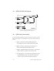
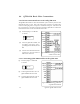
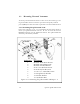
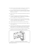
Figure 3.3.1.2-- Mounting the QTM-24ANT-SW Step 7
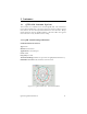
(1) Route the antenna cable through the mounting plate as shown in Fig-
ure 3.3.1. DO NOT snap the antenna to the mounting plate yet.
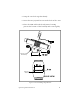
(2) Secure the molded antenna mount to the mounting plate as shown in
Figure 3.3.1. 1 Use the #8-32 x 5/8” machine screws and the #8-32 SS/
Nylon hex nut as shown.
(3) Snap the antenna into the mounting plate (dashed lines) as shown in
Figure 3.3.1.1
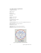
(4) Secure the articulated arm to the molded antenna mount using a
1/4-20 x 1-1/4” machine screw, a 1/4” flat washer. a 1/4” lock washer,
and a 1/4-20 SS hex nut as shown in Figure 3.3.1.1.
(5) Secure the molded wall/mast mount to the articulating arm using a
1/4-20 x 1-1/4” machine screw, a 1/4” flat washer, a 1/4” lock washer,
and a 1/4-20 SS hex nut as shown in Figure 3.3.1.1.
(6) Adjust the length of the cable to minimize the exposed cable loop.
(7) Place the cable guard over the exposed cable and snap it in place, as
shown in Figure 3.3.1.2.
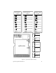
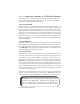
(8) To mount the assembly, drill four (4) 3/16” diameter (M4.75) pilot holes
for the wall anchors. Use the molded wall/mast mount as a template to
drill your holes. Or, cut out the hole template provided on page 45.
(9) Loosen the screws in the boom arm to adjust the antenna position.
Tighten the screws when the optimum position is determined.