
User's Manual

B&B Electronics, Inc. APPN-TT551 Databook
8
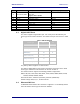
4.0 Pin out and Connectors
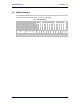
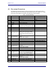
Pin definition is dependent upon the device type selected. The specific pin function is
defined in Table 2 for each device type. Where multiple options are available for a single
device type, these options are software selectable by the device firmware.
Table 2 – Module Pin Definition
Pin Signal Description PCIe Pin Mapping
1 V
SS
Ground 9,15,21,27,29,35,50,40,34,26,18,4
2 Not Used Not Used
3 DV
DD
Power, +3.3 V 2,24,52
4 DV
DD
Power, +3.3 V 2,24,52
5 Not Used Not Used
6 DBG_TXD Debug serial transmit data 30
7 #RESET
Reset active low input. A transition to high
releases the reset condition (see “Reset” in the
Data book). There is a weak pull-up on this pin.
22
8 DBG_RXD Debug serial receive data 32
9 Not Used Not Used
10 Not Used Not Used
11 #DEFAULT/LED_LINK
At boot, restore factory default active low input.
LAN link or serial connection detected LED
output. May be used as digital input or 3.3 V
CMOS-compatible digital output (V
OL
≤0.4, 2.4
V≤ V
OH
).
45
12 UART_CTS1/SPI_SEL
Primary UART clear to send input or SPI select
output
Signal is LVTTL-compatible.
36
13 LAN_RX+ LAN receive positive Not Used
14 LAN_RX- LAN receive negative Not Used
15
V
SS
Ground
9,15,21,27,29,35,50,40,34,26,18,4
16 V
SS
Ground
9,15,21,27,29,35,50,40,34,26,18,4
17 Not Used Not Used
18 UART_RTS1/SPI_CLK
Primary UART request to send output or SPI
clock input
Signal is LVTTL-Compatible.
38
19 Not Used Not Used
20 Not Used Not Used
21 Not Used Not Used
22 SRL_MODE/SPI_INT
Serial transceiver protocol select output or SPI
interrupt output (see Error! Reference source
not found.). Signal is LVTTL-Compatible.
47
23 LED_CONNECT Wireless TCP session established LED output 20
24 UART_RXD1/SPI_MOSI
Primary UART receive data input or SPI slave
data input.
Signal is LVTTL-Compatible.
51
25 LED_POST Power-on self-test LED output 44
26 LED_WLAN_CFG Wireless IP address assigned LED output 46
27 Not Used Not Used