B&K Components, Ltd. AVR101 series 100 AVR202 series 200 A/V Receiver Owner’s Manual p/n 12699 Rev.
B&K Components, Ltd., 2100 Old Union Road, Buffalo, New York 14227-2725 p/n 12699 Rev.
TABLE OF CONTENTS Acknowledgments . . . . . . . . . . . . . . . . . . . . . . . . . . . . . . . . . . . . . . . . . . . . . . . . . . . . . . . . . . . . . . . . . . . . . . . . . . . . . . . 2 Safety Precautions . . . . . . . . . . . . . . . . . . . . . . . . . . . . . . . . . . . . . . . . . . . . . . . . . . . . . . . . . . . . . . . . . . . . . . . . . . . . . . 3 Features . . . . . . . . . . . . . . . . . . . . . . . . . . . . . . . . . . . . . . . . . . . . . . . . . . . . . . . . . . . . . . . . . .
ACKNOWLEDGMENTS Manufactured under license from Dolby Laboratories. “Dolby”, ”Pro Logic”, “AC-3", and the double-D symbol are trademarks of Dolby Laboratories. Confidential Unpublished Works. © 1992-1997 Dolby Laboratories, Inc. All rights reserved. DTS® is a registered trademark of Digital Theater Systems, LLC. Additionally licensed under the following US Patent 5,451,942 & National Patent applications derived from PCT/US95/00959. Additional U.S. and Foreign Patents pending.
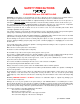
SAFETY PRECAUTIONS PLEASE READ BEFORE INSTALLING WARNING: to prevent fire or shock hazard, do not expose this unit to rain or moisture. Care should be taken to prevent objects or liquid from entering the enclosure. Never handle the power cord with wet hands. The lightning flash with arrowhead, within an equilateral triangle, is intended to alert the user of the presence of uninsulated “dangerous voltage” within the product’s enclosure that may constitute a risk of electric shock to you.
FEATURES Your new receiver is a versatile audio/video control center. The receiver is designed to sound sensational and be an attractive, easy-to-use addition to your audio/video system. Although you already have a good idea of your receiver’s features, we would like to take a moment to point out certain highlights. Remote Control - easy control of your B&K equipment. Front Panel Operation - nearly all functions can be controlled directly from receiver.
THE BASICS The following is intended to familiarize users with common terms and applications of Home Theater equipment. Sources - your receiver can directly provide audio from its built-in AM/FM tuner. It can also provide limited video from its on-screen menu system. Typically you will want to connect a number of additional sources (VCR, DVD player, etc.) to your receiver. Your receiver is designed to accomodate a wide range of audio and video signals.
Mode”). Since all modern sources are stereo, the mono information is usually replicated on both the left and right channels. Stereo - Stereo contains two discrete, full range audio channels. This is the most common format for music and is also used on many movies. You may get stereo from any source - digital or analog. Sound will normally come only from your front left and right speakers, but your receiver can additionally produce stereo in four or five channels (see “Surround Mode”).
Bass Management - Dolby Digital and DTS formats contain up to 5 full range channels plus LFE. Only a system with five full-range (large) speakers plus a subwoofer can directly reproduce these formats. However, almost all commercially available center channel speakers are small and incapable of reproducing the lowest bass frequencies without distortion or even damage to the speaker. Many people also use small speakers in the rear of their system, while others use small speakers all around.
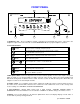
FRONT PANEL 6 B & K Components, Ltd. 5 1FB " " CUbYUc " >2DE6C =6G6= 46?E6C =6G6= C62C =6G6= DF3 =6G6= K@?6 # HEADPHONE C<55@ @B5C5D 5>D5B =5>E 4?G> E@ C?EB35 1 F B5359F5B =?45 <5F5< ↵ @?G5B ?> ?66 1 2 3 4 1. Headphone Jack - Stereo headphones having a standard ¼ inch binaural plug can be connected to the headphone output. The receiver must be on and in HEADPHONE Mode for proper headphone operation. 2.
REAR PANEL The receiver’s back panel is organized into groups of inputs and outputs for audio and video as shown below. See back of this manual for an enlarged view. 1. AC fuse holder - Holds the AC Line fuse. Replace only with 12 Amp / 250 Volt Slow Blow fuse. 2. AC input receptacle - For attaching the supplied AC power cord to the receiver. 3. RS-232 input (optional) - For future interface applications. 4. Speaker outputs - Connections for your speakers.
MAKING THE CONNECTION It’s tempting to just plug in your new receiver and have great sound pour out. Before you do that, take a few minutes to plan out how you want the receiver to fit into your audio/video system. Ask yourself the following questions: y y What source components do I want to connect to my receiver? (CD, VCR, etc.) What equipment will be receiving the audio and video? (TV monitor, Speakers, etc.
AUDIO / VIDEO CONNECTIONS Connecting your analog sources to your receiver Audio / Video source - connecting a DVD/VLD player to the receiver’s analog inputs. Use the same instructions for connecting to other audio / video sources such as a television, satellite receiver, cable box, etc.
DIGITAL CONNECTIONS Connect digital inputs (DVD, VLD, etc.) to the receiver. You will need either coaxial or optical digital inputs to play Dolby Digital (AC-3) or DTS surround sound processing. Digital connections are also recommended for PCM sources. If your source has both optical and coaxial outputs connect only one. COAX DIGITAL INPUTS TV-V3 V2 V1 Coaxial digital inputs - standard RCA type connectors.
SPEAKER OUTPUTS Five-way binding posts are provided, one pair for each channel. They are designed to accept a banana-type plug or spade lug connector (shown below) and are color coded for easy identification. The red (+) post should always be connected to the speaker’s red (+) jack. The black (-) post should always be connected to the speaker’s black (-) jack. Spade connector Banana jack The amplifier section of the receiver will produce 105 watts / channel into 8 ohms.
ANTENNA CONNECTIONS TUNER The FM jack is a standard screw on F-type connector. The AM is a push type. Strip ¼ inch of insulation off your AM antenna wires and insert one wire end into each hole while holding the tabs down. Release the tabs to lock in the AM antenna wires. FM antenna FM Antenna Input from Indoor/Outdoor Antenna, Cable Box, etc. AM Antenna Input from Loop Antenna AM antenna CONTROL OUTPUTS / IR INPUTS CONTROL OUT 1 2 +12VDC 50mA IR IN Z1 3.5 mm control output to amplifier, etc.
FREQUENTLY ASKED QUESTIONS My collection of equipment differs from the labels on the back of my receiver, how can I hook them up? Your receiver provides 5 identical sets of inputs - V1, V2, DVD, CD, and SAT. Each of these has analog audio, composite video, S-video, coaxial digital audio, and optical digital audio. It is convenient to connect components as labeled on the back of your receiver, but since all the inputs are identical, you can connect any compatible source to any set of inputs.
My laserdisc player (or other digital source) has only optical output, but my CD recorder (or other digital recorder) has only coaxial input. Do I need some sort of converter to make direct digital recordings? No, your receiver will convert optical to coaxial and coaxial to optical. The currently selected digital input (optical or coaxial) will appear at both of the receiver’s digital outputs (optical and coaxial). Do I need to connect both analog and digital audio from my receiver to my CD, DAT, MD, etc.
SETUP For best results, perform the following set up procedure when you initially install your receiver and anytime you change or add sources, speakers, etc. or when you rearrange your listening area THE MENU SYSTEM Setup of your receiver will require you to navigate through the menu system. We recommend that you use a video monitor connected to the zone 1 output along with the remote control provided with your receiver. It is also possible to set up your receiver from the front panel.
USER PREFERENCE SETUP You should always perform USER PREFERENCE SETUP after first installing your receiver and after adding/changing sources or video monitors. Be sure your main power is switched on from the front panel. For correct zone 1 video operation it is important that you perform the first step - DISPLAY OPTIONS - Z1 VIDEO MONITOR. Other USER PREFERENCE setups are less important - the factory setting will work fine for most users.
Set your Zone 1 video monitor type - You should do this first so that you will get the best possible display while performing the rest of the setup procedure.
Set the intensity of on-screen video overlays - Overlays will appear when you change a receiver setting or your receiver detects a change in the incoming audio or video information. Transparent mode allows video to be seen behind the overlay.
Set the tuner video - This allows you to view a TV/FM simulcast or watch a network sports broadcast while listening to your local radio announcer. You can set any of the seven external sources. You can also choose “last”. In “last” mode the tuner video will be from whatever source you watched before switching to TUNER. The final choice for tuner video is off. In zone 1 “off” will cause the background color to be displayed. Zone 2 has no on-screen display capability so off is truly off.
Edit Source Name From the factory, your receiver will display source names that match those printed on the rear of the receiver and on the supplied remote. However, this menu allows you to change the displayed names to match the actual sources used. If you do not want to change the names then skip this step. Note that the tuner name cannot be changed. Check that you are in USER PREFERENCE SETUP and that the remote is in AUDIO mode.
USER PREFERENCE SETUP 1 2 3 4 SURROUND MODE OPERATION 1 Surround Operation Auto Dolby Digital / DTS 5.
SETUP/CONFIGURE You should always perform Setup/Configure after first installing your receiver and after adding/changing speakers or sources or rearranging your listening area. If you have just completed the USER PREFERENCE SETUP above you are already in the MAIN MENU. If not, follow the instructions above to get to the MAIN MENU. Check that the remote is in AUDIO mode.
Set The size for your front left/right speakers - OFF is not a choice - you must have front speakers. SETUP MENUS 1 2 3 4 5 Speaker Speaker Source AM Tuner FM Tuner ↑ ↓ SEL MENU 1 2 3 4 5 6 7 Size and Delay Calibration Levels Channels Channels move to new line select menu page previous page SPEAKER SIZE SETUP Front L/R Small Center Small Rear L/R Small Subwoofer Yes LFE Normal Center Delay 0 ms Rear Delay 0 ms move to new line ↑ ↓ adjust parameter ←→ M E N U previous page 63($.
Set the size for your rear left/right speakers 1 2 3 4 5 6 7 SPEAKER SIZE SETUP Front L/R Small Center Small Rear L/R Small Subwoofer Yes LFE Normal Center Delay 0 ms Rear Delay 0 ms move to new line ↑ ↓ adjust parameter ←→ M E N U previous page 5($5 / 5 60$// From Remote 1 (PAUSE) or (STOP) 2 (REW) or (FF) Rear setting From Front Panel Action ∧ (UP) or ∨ (DOWN) move to Rear L / R VOLUME KNOB choose speaker size Subwoofer Ultra Subwoofer On Subwoofer Off Front Large Subwoofer Off Front Sma
Setup your LFE channel - Usually this will be set to NORMAL. However, if you prefer less LFE you can reduce the level or completely turn off the LFE channel. Note that this affects only the separate LFE channel available on Dolby Digital and DTS material it has no effect on the reproduction of normal bass from the front, center, or rear channels. If you have no subwoofer you may wish to reduce or turn off the LFE channel to reduce its contribution to the bass going to your front speakers.
Speaker Calibration Speaker calibration allows you to equalize the volume levels of each speaker to make up for differences in speaker characteristics and distances from the listener to the speakers. For best results it is important that you perform this calibration when you initially install your receiver, whenever you change speakers, and whenever you rearrange your listening area. You may use a Sound Pressure Level (SPL) meter to perform this calibration or just use your ears.
Source Levels This setup allows you to match the levels of your sources so that there are no large changes in volume as you change from one source to another. This is for your convenience only and need not be performed unless you wish to. You may use a SPL meter or your ear to adjust the levels. Note that the levels will depend not only on this setting but also on the source material being played back. You may wish to use a test disc. Make sure you are in the SETUP MENUS and your remote is in AUDIO mode.
SETUP MENUS 1 2 3 4 5 Speaker Speaker Source AM Tuner FM Tuner ↑ ↓ SEL MENU AM TUNER SETTINGS Size and Delay Calibration Levels Channels Channels AM ↑ ↓ ←→ MENU move to new line select menu page previous page $0 781(5 6(783 From Remote 550 $0 Channel 0 change channel change frequency previous page &K From Front Panel Action 1 (PAUSE) or (STOP) ∧ (UP) or ∨ (DOWN) move to AM Tuner Channels 2 SEL or ENTER ↵ (ENTER) activate AM TUNER SETTINGS 3 (PAUSE) or (STOP) ∧ (UP) or ∨ (DOWN
OPERATION The following outlines the normal day-to-day operation of your receiver from the supplied universal remote or directly from your receiver’s front panel. The universal remote is also capable of controlling other equipment and storing sequences of commonly used commands. Refer to the separate remote manual for details on these functions. POWER ON/OFF The main power switch on the front panel of your receiver must be on for the receiver to operate.
CHOOSING A SOURCE In general, the selected source will appear at the ZONE 1 output, the TAPE output, and the V1 output. To prevent feedback, TAPE input will not appear at TAPE output and V1 input will not appear at V1 output. DVD Source Composite Video DVD PCM 2.
ADJUSTING THE VOLUME MASTER LEVEL Master Volume 92/80( '% 0 dB MASTER LEVEL From Remote From Front Panel Action VOL ∧ or VOL ∨ VOLUME KNOB adjust volume MUTE can’t do from front panel instant volume all the way down press MUTE again to restore Note: The front panel VOLUME KNOB is used to control multiple functions and, therefore, cannot always control the volume. MASTER LEVEL will light to let you know when the VOLUME KNOB will control volume.
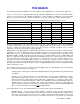
SURROUND MODES Your receiver provides a number of listening modes. The following table shows how your receiver responds to the chosen surround mode setting for various types of source material. The table assumes five full range speakers plus a subwoofer. If your speaker configuration is different from this make sure you have performed the set up procedures described previously.
Surround Modes (cont.) DVD Source Composite Video DVD PCM 2.0 Pro Logic '9' 352 /2*,& From Remote From Front Panel Action MODE (MODE) step to desired mode Note: your receiver keeps track of a surround mode for each of the sources. It would be possible, for example, to have your DVD player set to SURROUND while your CD player is set to STEREO. All you need to do is change sources and the surround mode you last used for that source will be recalled.
OVERRIDES Some laserdiscs contain the normal movie soundtrack on the PCM, AC-3 RF or DTS digital soundtrack along with supplemental information on the laserdisc’s analog track. Your receiver will automatically select the digital track if one is available. In order to reach the analog track we have provided an analog override to force the receiver to ignore the digital soundtrack. Note that your laserdisc player normally puts out converted digital soundtracks on its analog output.
Recalling a Preset Preset 0 Music Video TV-V3 Surround 0dB 086,& 9,'(2 Press SEL to Recall From Remote From Front Panel Action 1 number or A + number (PRESET) step to desired preset review settings for recall 2 SEL or ENTER ↵ (ENTER) recall preset Saving a Preset SAVE PRESET A2 'Watch DVD/VLD' DVD Stereo Lt Rt 0. . A9 ↑ ↓ ←→ SEL MENU SAVE PRESET A2 Saving Current Settings -14 dB DVD change preset change character change position save preset previous page 0. .
GETTING RECEIVER STATUS If you are not in a menu, pressing ENTER will bring up a two-line status message. This display will also pop up automatically whenever you change sources or whenever the source information changes. The video type is very important if you are using mixed composite and S-video sources since it will tell you how you must set your monitor for the best picture. The bitstream and channel information is particularly important with DVDs since they may contain multiple soundtracks.
ADVANCED FEATURES WARNING - The following describes the advanced features of the receiver. Since changing some of these functions may cause severe effects such as no sound or no remote control operation, we suggest you leave this menu disabled (hidden) for normal operation. If you are unsure of what you are changing DO NOT perform any advanced operations. These features may be activated by simultaneously pressing the SLEEP, DOWN, and UP buttons on the front panel of the receiver.
ZONE CONFIGURATION Zone Configuration will allow you to set maximum volume levels for each zone, change remote control ID codes for each zone and turn off the on-screen display overlays in zone 1. Make sure you are in the ADVANCED SYSTEM SETUP menu and the remote is in AUDIO mode. Z1 Max Level - Z1 max level allows you to set a maximum volume level for zone 1.
Z1 / Z2 Product ID - Each message transmitted from your remote includes a Product Code, identifying the manufacturer, and a product ID code from 1 to 16. The product ID code allows multiple B&K products to be controlled from the same remote. Your receiver actually uses two product ID codes - one for zone 1 (normally set to ID code 1) and the other for zone 2 (normally set to ID code 2). If you have a system with multiple B&K products then you may wish to set the product ID codes to other values.
Z2 Level Control - You may wish to install an in-wall volume control in your second zone. This can cause confusion between your receiver’s internal zone 2 volume controls and your in-wall controls. You can set your receiver to provide a fixed level to zone 2 instead of the variable level. The fixed level can be used to limit the maximum volume in zone 2 but setting lower volumes must be done with the in-wall controls.
POWER ON TITLES When you turn your receiver on it displays two lines of text. You can change this text to a personalized message. Make sure you are in the ADVANCED SYSTEM SETUP menu and the remote is in AUDIO mode.
CONTROL OUT SETUP Your receiver’s control outputs allow you to control up to 4 external devices such as power amplifiers, projection screens, etc. The control outputs can be programmed on/off depending on which source is selected. They may also have global control for all sources for headphone listening or remote repeater functions. Control Out 1 - Control out 1 is dedicated to zone 1 it can be programmed to be on or off for each source.
Control Out 2, 3, and 4 - Control out 2, 3, and 4 can be used in either zone. For each source they can be programmed to be on when that source is selected in zone 1, zone 2, or both zones. If the source is selected in neither zone the control out will be off. Control outs 2, 3, and 4 can also be set to REMOTE. In REMOTE mode your receiver acts like a remote repeater - IR remote signals detected by your receiver are repeated on the control out. REMOTE mode is a global override for all sources.
TROUBLESHOOTING PROBLEM POSSIBLE CAUSE POSSIBLE SOLUTION No sound, display will not light 1. Power cord not plugged in. 2. Power off at AC source. 3. Power switch off. 4. AC power inlet fuse blown or faulty. * 1. Reconnect power cord. 2. Check power at plug. 3. Turn power switch on. 4. Check for shorts or overloading. Replace fuse. No sound, display on. 1. Receiver in mute 2. Volume control to minimum. 3. Wrong source selected. 4. Line stage to amp. cables loose or faulty. 5.
RECEIVER SPECIFICATIONS Video Specifications Audio Specifications Frequency Response: 5 Hz - 20 kHz , +0/−0.5dB Frequency Response: 20 Hz - 10 MHz ±3dB Input Sensitivity: 63 mV Maximum Input Level: 2 V P-P Maximum Output Level: 9 V rms Maximum Output Level: 2 V P-P Signal to Noise Ratio: 89 dB CCIR 2 k Weighted max level Input Impedance: 50 k Ohms Input Impedance: 75 Ohms Output Impedance: 221 Ohms Output Impedance: 75 Ohms Noise Test Reference Level: -12.
1 2 3 4 5 6 48 ↑ ↓ SEL MENU move to new line select menu page exit menu system MAIN MENU Help / Navigate Product Information Zone 2 Operation Edit Preset Title User Preferences Setup / Configure 6 5 4 3 2 1 1 2 3 4 5 6 1 2 3 4 Menu or Go Back New Line or Text Adjust or Cursor Select or Save Select or Save HELP GUIDE ' change preset change character change position save preset previous page change preset change character change position save preset previous page move to new line select menu
REAR PANEL ENLARGED VIEW 49 p/n 12699 Rev.
B&K Components, Ltd 2100 Old Union Road Buffalo, New York 14227 716-656-0023 www.bkcomp.com 50 p/n 12699 Rev.