
User Manual


Once one of these I-V curves has been selected and set from the front panel, the power supply
will operate in PV mode and output a voltage and current value according to the active I-V profile
and load conditions. Different points on the I-V curve will be output in 1 ms intervals to test the
inverter’s MPPT efficiency. To create a user-defined table of I-V points and simulate a change in
irradiance conditions (e.g. cloudy or rainy day), the PV supply must be controlled by the SAS
software. The SAS software also monitors and logs real-time voltage, current, and power as well
as real-time and average MPPT efficiency to validate the inverter’s MPPT algorithm.
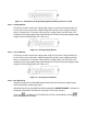
To configure and set the MR power supply to PV mode from the front panel, follow the steps
below:
1.
Press the button and press the button three times until PV SIMULATION is
select, then press . The following display will be shown:
1.
Use the keys to move the cursor to the ON/OFF field
and use the rotary knob to select
ON
or
OFF
.
ON means the MR
supply is set to PV mode.
2.
Use the keys to move the cursor to the CURVE field
and use the rotary knob to select
the desired curve number. The
curve number can be 1-101 or TABLE (table of up to 4096 I-V
points.)
3.
Once again, use the keys to move the cursor to the
EDIT field and press . The following display will be shown:
4.
Use the keys to move the cursor through the four
parameter settings. Use the
numerical keys to enter parameter
values and press
to confirm each of the four parameter
settings.
Press
several times to exit the menu setting.