
User Manual


2.
If entering using numeric keypad, press
first so that the
cursor selects the voltage display.
Then, enter the value and
press
to set the voltage.
3.
To change the cursor position to adjust with the voltage adjust knob, use the keys to
move left or right.
When output is ON, the user can use the rotary to adjust the voltage value when the output is in
constant voltage (CV) mode. The output value will change simultaneously with the adjusted value.
This is so called on-the-fly function that allows user to easily change the output value if the test is
needed.
3.2.2 Setting Current
Follow the steps below to set the output current:
1 From the normal front panel display, users can use either the current adjust knob or the
numeric keypad to enter the setting current.
2 If entering using numeric keypad, press first so that the cursor selects the current
display. Then, enter the value and press to set the current.
3 To change the cursor position to adjust with the voltage adjust knob, use the
keys to move left or right.
When output is ON, the user can use the rotary to adjust the current value when the output is in constant
current (CC) mode. The output value will change simultaneously with the adjusted value. This is so
called on-the-fly function that allows user to easily change the output
value if the test is needed.
3.2.3 Remote Sense
Remote sense can be used to compensate for voltage drops up to 5 V (MR25080) or 10V
(MR50040) or 20V (MR100020) due to resistance from test leads connected to your device under
test (DUT), thus providing more accurate output voltage. The power supply is initially set up for
local sense mode by default. Refer to the following sections for details of local and remote sense
setup.
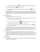
3.2.3.1 Local Sense
By default, the power supply is set up for local sense. This is determined by the wire connections
in the rear panel, illustrated below: