Safety Summary The following safety precautions apply to both operating and maintenance personnel and must be followed during all phases of operation, service, and repair of this instrument. Before applying power to this instrument: Read and understand the safety and operational information in this manual. Apply all the listed safety precautions. Verify that the voltage selector at the line power cord input is set to the correct line voltage.
Category IV (CAT IV): Measurement instruments whose measurement inputs are meant to be connected to the primary power entering a building or other outdoor wiring. Do not use this instrument in an electrical environment with a higher category rating than what is specified in this manual for this instrument. You must ensure that each accessory you use with this instrument has a category rating equal to or higher than the instrument's category rating to maintain the instrument's category rating.
Electrical Power This instrument is intended to be powered from a CATEGORY II mains power environment. The mains power should be 120 V RMS or 240 V RMS. Use only the power cord supplied with the instrument and ensure it is appropriate for your country of use. Ground the Instrument To minimize shock hazard, the instrument chassis and cabinet must be connected to an electrical safety ground. This instrument is grounded through the ground conductor of the supplied, threeconductor AC line power cable.
In air temperatures exceeding the specified operating temperatures. In atmospheric pressures outside the specified altitude limits or where the surrounding gas is not air. In environments with restricted cooling air flow, even if the air temperatures are within specifications. In direct sunlight. This instrument is intended to be used in an indoor pollution degree 2 environment. The operating temperature range is 0 °C to 40 °C and the operating humidity 90% relative humidity with no condensation allowed.
Instrument covers must not be removed by operating personnel. Component replacement and internal adjustments must be made by qualified service-trained maintenance personnel who are aware of the hazards involved when the instrument's covers and shields are removed. Under certain conditions, even with the power cord removed, dangerous voltages may exist when the covers are removed.
This instrument contains one or more cooling fans. For continued safe operation of the instrument, the air inlet and exhaust openings for these fans must not be blocked nor must accumulated dust or other debris be allowed to reduce air flow. Maintain at least 25 mm clearance around the sides of the instrument that contain air inlet and exhaust ports. If mounted in a rack, position power devices in the rack above the instrument to minimize instrument heating while rack mounted.
Compliance Statements Disposal of Old Electrical & Electronic Equipment (Applicable in the European Union and other European countries with separate collection systems) This product is subject to Directive 2002/96/EC of the European Parliament and the Council of the European Union on waste electrical and electronic equipment (WEEE), and in jurisdictions adopting that Directive, is marked as being put on the market after August 13, 2005, and should not be disposed of as unsorted municipal waste.
CE Declaration of Conformity This instrument meets the requirements of 2006/95/EC Low Voltage Directive and 2004/108/EC Electromagnetic Compatibility Directive with the following standards. Low Voltage Directive 1. UL 61010-1:2012 EMC Directive 2. EN 55011:2009+A2:2010 3. EN 61000-3-11: 2000 4. EN 61000-3-12: 2011 5. EN 61000-4-2 / -3 / -4 / -5 / -6 / -8 / -34 6. EN 61326-1: 2013 7.
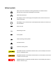
Safety Symbols Refer to the user manual for warning information to avoid hazard or personal injury and prevent damage to instrument. Electric Shock hazard On (Supply). This is the AC supply connect/disconnect switch on the front of the instrument. Off (Supply). This is the AC mains connect/disconnect switch on the front of the instrument.
Table ofContents Safety Summary ................................................................................................................. 1 Category rating ............................................................................................................................ 1 Compliance Statements ......................................................................................................... 7 CE Declaration of Conformity ..............................................................
3.1 3.2 3.3 3.4 3.5 3.6 3.7 3.8 3.9 3.10 3.11 3.12 3.13 3.14 4 Menu Options .................................................................................................................. 27 3.1.1 How to Access the Menu ................................................................................... 28 ConfigureVoltage/CurrentOutput ................................................................................... 28 3.2.1 Setting Voltage ........................................................
4.2 5 Calibration ..................................................................................................................... 67 5.1 5.2 5.3 5.4 5.5 5.6 5.7 5.8 6 Voltage Calibration .......................................................................................................... 68 Current Calibration ........................................................................................................... 69 OVP Calibration ...........................................................
1 General Information B&K Precision models MR25080, MR50040, and MR100020 are high voltage programmable DC power supplies with single outputs that offer the maximum power output up to 5000 watts (0 - 250 V / 80 A or 0 - 500 V / 40 A or 0 - 1000 V / 20 A). By connecting up to *50 power supplies in parallel, a maximum output power can reach up to 250 kW. These power supplies are fully programmable and controllable through analog programming, USB, RS232, RS485, GPIB and Ethernet interface.
18. 1 x Test Report Verify that all items above are included in the shipping container. If anything is missing, please contact B&K Precision. 1.3 Product Dimensions The MR25080, MR50040, and MR100020 power supply’s dimensions are approximately: 420mm (16.54in) x 88mm (3.46in) x 532mm (20.95in) (WxHxD). These 2U supplies are designed to fit in a standard 19-inch rackmount. Note: All dimensions in the figures below are measured in millimeters (mm). Figure 1.1 – Front Panel Dimensions Figure 1.
Figure 1.3 – Front Panel Overview 1.4.1 Front Panel Description 1 Power On/Off switch 2 Vacuum Fluorescent Display 3 LAN Status indicator 4 Keypad lock indicator 5 Function keys 6 Numeric keys 7 Function keys 8 Rotary Knob 9 Left, Right cursor keys 1.5 Keypad Overview Figure 1.4 – Keypad Overview 1.5.1 Keypad Description Shift key Enables access to secondary functions (Labeled in blue) On/Off Controls the output state.
Recall / Save button Saves and recalls instrument settings. Escape button Exits menu settings. Zero / Lock button Inputs a value of zero or locks the front panel buttons. Decimal / Local button Inputs a decimal point for values or sets the instrument back to local mode Numeric keypad Enters numeric values for various parameters. Menu button Allows access to the power supply menu settings. Program button Enters program mode settings menu. Enter Confirms setting/parameter changes.
1.6 Rear PanelOverview Figure 1.5 – Rear Panel Overview 1.6.
1.7 Display Overview Figure 1.6 – Display Overview 1.7.
2 Getting Started Before connecting and powering up the instrument, please review and go through the instructions in this chapter. 2.1 Input Power and Fuse Requirements 2.1.
1. First, connect the input receptacle (green terminal block) of the cable to the input terminals of the power supply. 2. Align the power cord housing mounting holes on the left and right side to the screw holes on the power supply. 3. Use only the included screws to fasten and secure the cable housing assembly. Figure 2.
Refer to the descriptions below to connect the other end of the AC power cord to the AC distribution panel. Do NOT plug the AC power cord into the wall socket prior to connecting ALL three AC power wires to the rear panel and securely mount the safety metal housing over the input receptacle. Doing so may create a shock hazard. Connection of this power supply to an AC power source should be made by a qualified electrician or other qualified personnel.
2.1.2 Fuse Replacement This power supply does not require a fuse that is user replaceable. There is an internal fuse, in which if blown, may indicate a malfunction in the unit. In this event, contact B&K Precision. Any disassembling of the case or changing the fuse not performed by an authorized service technician will void the warranty of the instrument. 2.
Table 1 – Wire Gauge Rating Before connecting wires to the output terminals, turnOFF the power supply to avoid damage to the instrument and the device under test (DUT). For safety, load wires must have a wire gauge size large enough to prevent overheating when the power supply operates at maximum short circuit output current. It will also prevent large voltage drops from resistances in the wires.
Follow the steps below to check voltage output with no load connected. 1. Turn ON the power supply. The display will show the OFF annunciator above the voltage display. 2. Enable the output by pressing annunciator will change to CV. , and the LED next to the button will be lit. The OFF 3. Using the numeric keypad or the voltage adjust knob and enter a voltage value. The voltage display will now show the value you entered. If entering with numeric keypad, press first, then enter the value and press . 4.
Follow the steps below to check current output of the power supply. 1. Turn ON the power supply. The display will show the OFF 2. annunciator above the voltage display. Be sure that the output is disabled (the LED next to the button should not be lit when it is off). If the LED is ON, press to disable output. Short the (+) and (-) output terminals with test leads, shorting bar, or clip. (Refer to “– Wire Gauge Rating” to select appropriate test leads) 3.
5. The UI firmware is shown above as 1.02. 6. Press once again and the firmware version will displayed. 7. The control firmware is shown above as 1.02. 8. Press once again and the firmware version will displayed. 9. The interface firmware is shown above as 1.01. 10. Press once again and the firmware version will displayed. 11. The PFC firmware is shown above as 1.52. 12. Press three times to exit the menu and return to the normal display.
3 Front PanelOperation 3.1 Menu Options All settings and parameters can be configured from the built-in menu system of the power supply. To access the menu, press . The menu system is divided into 5 sections and are organized as follows: CONFIGURATION LIMIT Configures voltage setting limits. PROTECT Configures OVP, OCP, OPP, CV to CC, and CC to CV protection. EXT CONTROL Configures external analog control. PARALLEL Configures parallel connection and master/slave mode.
3.1.1 How to Access the Menu Before using the instrument, it is important to be familiarized with its menu structure and learn how to view or change settings and parameters. Follow the steps below to guide you in selecting menu options. 1 From the normal display, press to enter the menu. 2 The selected item will be show. Use keys to move through the menu selections. 3 When the desired menu section is show, press the display when SYSTEM is selected. 4 The selected item will be show.
2. If entering using numeric keypad, press Then, enter the value and press first so that the cursor selects the voltage display. to set the voltage. 3. To changethe cursorpositiontoadjustwiththe voltage adjust knob, use the move left or right. keys to When output is ON, the user can use the rotary to adjust the voltage value when the output is in constant voltage (CV) mode. The output value will change simultaneously with the adjusted value.
Figure 3.1 – Local/Remote Sense Connection Diagram When local sense is selected, the positive lead (+) of the DC output is connected to the positive end (+) of the load and the negative lead (-) of the DC output is connected to the negative end (-) of the load. When this sensing mode is selected the wires connecting between DC outputs to the load must be as short as possible. The local sense is the default configuration. DO NOT disconnect the wires if remote sense is not used.
4 Power ON the power supply, and then configure and enable the output. The setup should look like the figure above. DO NOT at any time disconnect the wires from the Vs+ and Vs- terminals to the DUT while output is enabled (ON). Doing so may damage the power supply and cause unstable output. 3.3 Voltage/Current Measurement The display will show the set voltage and current values and the measured values of the output. System Messages The MR has built-in sensors to detect system conditions.
PFC not functioning correctly PFC ERROR ! POWER OFF ! Power supply is powering off OUTPUT SHORT CIRCUIT Output voltage drop too fast HW Fail BVbus Module hardware fail 3.4 CONFIG Menu All setup procedures and settings explained in this section can be accessed from the CONFIGURATION menu. To access this menu, press press , select CONFIGURATION, then . 3.4.
2 3 Use the keys to select the limit setting value of V max, V min,I max, andI min. Press to confirm selection. 4 Use the numerical keys to set the limit value and press 5 Press to confirm the setting. several times to exit the menu setting. 3.4.2 Protection Settings 3.4.2.1 Configure Over Voltage Protection (OVP) The MR over voltage protection utilizes a hardware comparator that quickly protects the instrument when the voltage presented at the output terminal exceeds the OVP setting voltage.
2. Press OVP. button one time until PROTECT is select and press 3. Press button one time until OCP is displayed, and press 4. Use numerical keys directly or use confirm the OCP value. 5. Press . The display will then show . keyswith rotary adjustment followed by to several times to exit the menu setting. When OCP protection is tripped during operation, the output will turn off and the following OCP status message will display: To clear the trip status, press once. 3.4.
To clear the trip status, press once. 3.4.3.1 Configure CV to CC Protection The MR CV to CC protection monitors the transition between constant voltage to constant current mode. If this event occurs, the output of the power supply will turn off. Follow the steps below to set the CV to CC Protection: 1. Press button, select CONFIGURATION, then press 2. Press OVP. button one time until PROTECT is select and press 3. Press button three times until CV -> CC is displayed and press 4.
4. Use rotary to select the CC->CV ON or OFF followed by 5. Press . several times to exit the menu setting. When CC to CV protection is tripped during operation, the output will turn off and the following CC to CV status message will display: To clear the trip status, press once. 3.4.4 External Analog Control To control or monitor the output of the power supply using external signals, refer to the following figure of the DB25 connector located in the rear panel.
Pin Signal 2 Ground 3 Ground 8 Local/Analog I/O I Description Open: Front panel control Short to ground: Rear analog control Input 0-5 V / 0-5 kΩ or 0-10 V / 0-10 kΩ 9 Voltage Program I 10 Current Program I Input 0-5 V / 0-5 kΩ or 0-10 V / 0-10 kΩ for current output setting, full scale input equals maximum output current 11 Voltage Monitor O Output 0-5 V / 0-10 V represents power supply output voltage, full scale output equals maximum output voltage 12 13 for voltage output setting,
Pin Signal 16 Power OK I/O O Description High: Output is ON Low: Output is OFF 22 Ground 23 Ground Output 0-5 V / 0-10 V represents power 24 Current Monitor O supply output current, full scale input equals maximum output current 3.4.5 External Control Setting If you want to use the external mode to control the power, you must enter the menu configures external analog control before entering the external mode. Follow the steps below: 1. Press button, select CONFIGURATION, then press . 2.
5. Press button to set Shut Off (Remote Inhibit). External Shut Off Description OFF The Inhibit input is ignored. LIVE Output follow the state of the Inhibit input. The output remains disabled. LATCH The latched INH status bit is cleared by sending the OUTPut:PROTection:CLEar command or press button from the front panel. 3.4.5.1 Local/Analog Control Pin 8 can be used to select the control mode (local or analog) of the power supply’s output.
12. Hardware protection 3.5 Voltage Program 3.5.1 Voltage Mode Under voltage mode, the user may control the full scale output voltage value through Pin 9, by inputting a voltage level of 0-5 V (0-5 V / 0-5 kΩ mode) or 0-10 V (0-10 V / 0-10 kΩ mode) as shown below. Figure 3.4 – Analog Voltage Programming (Voltage Mode) 0-5 V or 0-10 V 3.5.
Figure 3.7 - Analog Current Programming (Resistor Mode) 0-5 kΩ or 0-10 kΩ 3.5.2.4 Voltage Monitor This function is able to monitor the voltage output using Pin 11 and one of the ground pins (i.e. Pin 22), which can be connected to a digital voltage meter (DVM) or other voltage monitoring device, as shown below. The output control must be in analog mode to use this function.
Note: Shut off can only occur when the power supply receives a trigger. Maintaining that pin constantly open will not trigger a shut off. 3.6 Parallel Operation Connection and Setup The MR power supplies can be connected in parallel to increase the power output capability as well as the output current. Up to *50 units of the same model can be connected for output up to 250 kW (max). To connect multiple units in parallel, follow the diagram shown below: Figure 3.
searching for all Slaves that are connected to the Master. To operate correctly, the user must set up the Slaves before the Master. Follow the steps below to set a supply to master or slave mode (Note: Multi-unit connection (chain) mode will be cancelled). 1 Press the button and press the button one time until PARALLEL is select and press . 2 Press to select the parallel MODE.
Slave Unit When a power supply is set up to be a slave unit, it will wait for the master’s connection, as shown below. If the master unit has found the slave unit, the slave unit will be controlled by the master unit and the following will be displayed: In parallel mode, the slave unit is remote controlled by the master unit. The keypad will be locked. To exit the parallel mode, press key to access the parallel mode ON/OFF setting in the menu. Turn off to disable parallel mode control. 3.6.
While in parallel connection mode, the output voltage of each power supply should be set to equal value. If the voltage value of each unit is not the same, the higher output voltage will feed back to the lower voltage unit and damage its internal components. DO NOT connect multiple power supplies in series as it will cause damage or malfunction. When connecting in parallel mode, only the MASTER unit can be controlled by a computer for remote communication.
3.7 PV Simulation Typically, a solar array is connected to an inverter, which converts the panel’s output from DC to AC. Due to varying environmental conditions and the nonlinear output of solar cells, many inverters use a maximum power point tracking mechanism to maximize the power generated from the solar panel. Using an actual solar array to test inverters is not cost-effective and environmental conditions are difficult to control in this scenario.
Once one of these I-V curves has been selected and set from the front panel, the power supply will operate in PV mode and output a voltage and current value according to the active I-V profile and load conditions. Different points on the I-V curve will be output in 1 ms intervals to test the inverter’s MPPT efficiency. To create a user-defined table of I-V points and simulate a change in irradiance conditions (e.g. cloudy or rainy day), the PV supply must be controlled by the SAS software.
3.8 Power-On State The initial Power-On state of the power supply can be configured (voltage, current, output state) by following the steps below: 1. From the menu, press button 3 times to select POWER-ON STATE and press 2. The mode is showing on the display, press selected using the rotary knob: . button. There are four options which can be DISABLE – Last voltage and current values before power off and output state is OFF. *RST – Reset output settings, voltage, current, output state, slew rate.
3.10.2 Restore Factory Default Settings All instrument settings can be reset back to their factory default values by doing the following: Note: Restoring the instrument to factory default will change all current instrument settings and parameters back to their default values. 1. From theSYSTEMmenu,press button 3 times to select DEFAULT and press . 2. The instrument will return to the normal display and all settings are now restored back to factory default.
Item Parameter HHH:MM:SS MR25080 MR50040 MR100020 000:00:00 000:00:00 000:00:00 OFF OFF OFF 0 0 0 Mode OFF OFF OFF Curve 1 1 1 CC CC CC Mode Disable Disable Disable MEM 1 1 1 Output State OFF OFF OFF Beep Mode ON ON ON Limit VMAX 255.0 V 510.0 V 1020.0 V VMIN 0.0 V 0.0 V 0.0 V IMAX 81.6A 40.8 A 20.4 A IMIN 0.0A 0.0 A 0.000 A 1 1 1 Mode Program PV Simulation.
Item Parameter MR25080 MR50040 MR100020 Gateway address 0.0.0.0 0.0.0.0 0.0.0.0 DNS 8.8.8.8 8.8.8.8 8.8.8.8 Hostname Model Model Model 1 1 1 Conflict Number Table 2 - Factory Default Settings 3.11 Save/Recall Instrument Settings The instrument can save up to 10 voltage/current values for quick 3.11.1 Save Settings 1. Set up output voltage and current settings that you want to save. 2. Then, press and . The display will show the following: 3.
2. Use the keypad to enter the memory location you want to recall. Enter a value between 1 and 10. The voltage and current settings of that memory location will be shown on the bottom of the display. 3. Once entered, the saved settings at the location will be immediately recalled. Note: When in Recall mode, users can recall settings from different locations without having to press additional keys each time.
Users also have the ability to utilize the REPEAT and NEXT options. The REPEAT option allows the user to execute the same program as many times, continuously, as needed. The NEXT option allows the user to select the next program to execute once the current program ends. Please be aware that REPEAT and NEXT options are part of a program, so if one program’s NEXT option is pointed to a previous program, the power supply will cycle these programs infinitely.
6. Press to select NEXT parameter and use the rotary knob to select a value of 0-10. As described previously, the user has the ability to queue another program once the current program is finished. By default, 0 is placed as the parameter value, and represent end the program. 7. Press to select STEP_EDIT parameter, pressing , the following will be displayed: 8. As described previously, each step has the following parameters to be edited: voltage, current, and time.
When program mode is running. The current program (1-0 : 1), step (1-0 : 0) and repeat number (0/3 : 3 ) will also show on the display. Where p is the program number, step (1-0 : 0) is the step number, repeat number (0/3 : 0 ) is the present repeated number and repeat number (0/3 : 3 ) is the total repeat number. For example, if the repeat number is 1/3, this means that there are three repeats of this program and it is now running the first repeat. 3.
3.14 Slew RateSetting The power supply has the capability of controlling the output voltage and current slew rate. The timing can be configured for the rising/falling edge between voltage and current output transitions. Follow the steps below to configure the voltage or current slope. 19. Press and buttons to enter the slope menu. 20. Use the buttons to select VOLTAGE or CURRENT and press following will be displayed: 21. Use the keypad or rotary knob to enter the slope value and press 22.
4 Remote Operation There are several interfaces available for remote communication: USB, RS232, GPIB, Ethernet, and RS485. With all these interfaces, this power supply is very flexible to be controlled remotely. Users can program the power supply by using the SCPI (Standard Commands for Programmable Instruments) commands over any one of the remote interfaces. This section will describe how to set up all of the supported interfaces.
4.1.2 USBVCP: The USBVCP is a virtual COM port that can be used for remote communication. There are no settings in the menu system for USB configuration. To configure the USBVCP settings, refer to the RS232 settings below, as they are the same. 4.1.3 USBTMC: When USB port select USBTMC-compliant (refer to the USBVCP settings) and can be used for remote communication and control. There are no additional settings in the menu system for USB configuration.
are sent too fast to the power supply, the internal buffer may overrun and cause a communication error. Therefore, a delay between commands to let the power supply have enough time to process them is mandatory. All serial settings must match the settings configured on the PC in order for communication to link successfully. 4.1.5 GPIB Each model can be configured with a GPIB address from 1-30. Follow the instructions below to select and configure the GPIB interface for remote operation. 1.
4.1.6 RS485 The MR series supports multiple power supplies (of the same model, up to *50) that can be connected together via RS485 and be controlled with a computer via USB (virtual COM) interface (Chain mode). If connecting more than 10 units, add a 120Ω resistor terminator to the last unit as shown in the figure below. Follow the instructions below to select and configure the RS485 interface for remote operation. Figure 4.1 – RS485 Connection Diagram for 10+ Units 4.
8. Press to save each setting and the display will return to the RS485 menu. 9. Below lists the options that can be changed for each setting: 10. Baud rate: 9600, 19200, 38400, 57600 11. Note: The default is 9600, None/8 bits, 1, Address = 1, Off. 12. For each power supply that you want to control, provide a different address. For example, if you have three power supplies to control, set the first supply to address 1, second supply to address 2, and third supply to address 3.
3. Use keys to select between each settings and press corresponding setting. to configure the 4. To change any of the parameter settings, use the rotary dial. 5. Press to save each setting and the display will return to the LAN menu. 6. The following lists the options that can be changed for each setting: Mode: DHCP, MANUAL IP Addr: 000.000.000.000 Subnet: 000.000.000.000 Gateway: 000.000.000.000 DNS: 000.000.000.000 4.1.
Figure 4.2 – Web Server Login Page 6. A password is required to login and access the menu items on the page. The default admin password 123456. The web server menu items are described below: 4.1.8.
Figure 4.4 – Web Server LAN Configuration Page 4.1.8.3 CONFIG page The CONFIG page provides the protection settings (OVP, OCP, OPP, CV to CC, and CC to CV) and output related parameters such as voltage/current slope and limit settings. Figure 4.5 – Web Server Configuration Page 4.1.8.4 CONTROL page The CONTROL page provides the general control of the power supply such as output On/Off setting as well as the voltage and current setting. The command line for SCPI commands can also be accessed here.
Figure 4.6 – Web Server Control Page The Log Out will exit the web page and go back to Home page. 4.1.8.5 Socket connection Socket connection is available for communication via LAN (Ethernet) interface. The instrument uses the TCP/IP protocol for communication. Users can use socket port 5025 to open a raw socket connection for sending remote commands. 4.2 Error/Event List SCPI interface can offer an error/event list that contains up to 20 errors/events.
-109 Missing Parameter -110 Command header error -111 Header separator error -113 Undefined header -131 Invalid suffix -138 Suffix not allowed -200 Execution error -203 Command protected -221 Settings conflict -222 Data out of range -223 Too much data -240 Hardware error -350 Error queue overflow
5 Calibration B&K Precision recommends a calibration interval of one year to ensure that the power supply meets specifications. This instrument features closed-case calibration. To perform the calibration, the following equipment is required: 5 ½ digit digital multimeter (DMM); B&K Precision 5491B or equivalent The following calibration instructions may be used by authorized technicians or calibration personnel only.
FACTORY CAL. DATA RESTORE These options are only accessible in the calibration menu. The following calibration procedures assume the operator is in the CAL menu. 5.1 Voltage Calibration Follow the steps below to perform the voltage calibration: 1. Connect the DMM to the output of the power supply as shown in the figure below: Figure 5.1 – Voltage Calibration Diagram When only calibrate local sense, connect the DMM to the output.
5.2 Current Calibration Follow the steps below to perform the current calibration: 1. Connect the shunt resistance, DMM and Electronic load to the output of the power supply as shown in the figure below: Figure 5.2 – Current Calibration Diagram 2. Set the DMM to a DC voltage measurement. Set the Electric Load in CV mode, the voltage set 5V. Select the CURRENT parameter in the Calibration menu and press bedisplayed: .
2. Select the OVP parameter in the CAL menu and press 3. Press to run the OVP calibration or press process that will take about 10 to 20 seconds. .The following will be displayed: to abort. The OVP calibration is an automatic 4. After the calibration is finished, the following message will be displayed: 5.4 OCP Calibration The overcurrent protection (OCP) can be executed right after the current calibration or the user can select OCP in the Calibration menu.
3. Press to run the OCP calibration or press process that will take about 20 to 30 seconds. to abort. The OCP calibration is an automatic 4. After the calibration is finished, the following message will be displayed: 5.5 External Voltage Programming Calibration Follow the steps below to perform the external voltage programming calibration: 1.
5.6 External Current Programming Calibration Follow the steps below to perform the external current programming calibration: 1. Connect the DMM to the external analog control terminals of DB25 connector (+ on the DMM to Pins 10 and 24, - on the DMM to Pin 22(GND)) on the rear of the power supply, asshown in the figure below: Figure 5.5 – External Current Programming Calibration Diagram 2. Set the DMM to a DC voltage measurement. Select the EXT CURRENT parameter in the CAL menu and press .
Figure 5.6 – CC Calibration of External Voltage Diagram 2. Select the EXT VOLTAGE CC parameter in the Calibration menu and press bedisplayed: . The following will The P: 1/4signifies there are 4 points to be calibrated and the current calibration point is 1. The four points use 0Ω, 2.5kΩ, 7.5kΩ, 10kΩ. 3. Press , the calibration will start, if the resister is not insert or not correct, the following will bedisplayed: 4. If the resister is correct, the following will bedisplayed, press . 5.
Figure 5.7 – CC Calibration of External Current Diagram 2. Select the EXT CURRENT CC parameter in the Calibration menu and press be displayed: . The following will The P: 1/4signifies there are 4 points to be calibrated and the current calibration point is 1. The four points use 0Ω, 2.5kΩ, 7.5kΩ, 10kΩ. 6. Press , the calibration will start, if the resister is not insert or not correct, the following will bedisplayed: 7. If the resister is correct, the following will bedisplayed, press . 8.
6 Troubleshooting Guide Below are some frequently asked questions and answers. Please check if any apply to your power supply before contacting B&K Precision. 6.1 General Q: I cannot power up the power supply. Check that the power cord is securely connected to the AC input and there is live power from your electrical AC outlet. Verify that the AC power coming from the mains contains the correct voltage. The power supply can accept a specific range of AC input voltages. Refer to section 2.1.
High Voltage Multi-Range DC Power Supplies MR Series Specifications Note: All specifications apply to the unit after a temperature stabilization time of 15 minutes over an ambient temperature range of 23 °C ± 5 °C. Specifications are valid for single unit operation only.
7 SERVICE INFORMATION Warranty Service: Please go to the support and service section on our website at www.bkprecision.com to obtain a RMA #. Return the product in the original packaging with proof of purchase to the address below. Clearly state on the RMA the performance problem and return any leads, probes, connectors and accessories that you are using with the device. Non-Warranty Service: Please go to the support and service section on our website at www.bkprecision.com to obtain a RMA #.
LIMITED THREE YEAR WARRANTY B&K Precision Corp. warrants to the original purchaser that its products and the component parts thereof, will be free from defects in workmanship and materials for a period of three years from date of purchase. B&K Precision Corp. will, without charge, repair or replace, at its option, defective product or component parts. Returned product must be accompanied by proof of the purchase date in the form of a sales receipt.
22820 Savi Ranch Parkway Yorba Linda, CA 92887 www.bkprecision.com © 2018 - 2019 B&K Precision Corp.