
User Manual

93
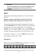
use the GPIO? query command. It will return the decimal
representation of the 8-bits binary that represents all the pins. The
pins with bit value “1” have 5 V at the input, and “0” for 0 V at input.
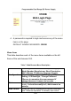
For example, suppose all pins are set as INPUT pins, but only pin 2
and 1 have a 5 V logic high (1) signal, then only these two pins
return “1” and the rest “0”. Sending GPIO? command will return: 3.
The complete 8-bit binary would be 00000011.
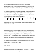
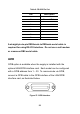
Pin
9
8
7
6
5
4
3
2
1
0
0
0
0
-
0
0
1
1
Note if there are output pins configured, those pins are ignored and
will have the value “0”.
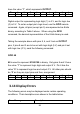
OUTPUT
To setup any of the 8 pins (except pin 5) as output pins, the remote
command GPIO:DIR is used. All pins (except pin 5) are represented
as 8-bits binary, according to Table 5 above. A “1” represents
OUTPUT, and a “0” represents INPUT. When using the GPIO:DIR
command, the decimal representation of the 8-bits binary is used.
For example, to set pins 8, 6, and 3 as OUTPUT pins, their values
must be set to 1, and the rest 0. Send:
GPIO:DIR 84
84 is used to represent 01010100 in binary. Only pins 8, 6, and 3