Model: 9110, 9111 Multi Range DC Power Supply USER MANUAL 1
Safety Summary The following safety precautions apply to both operating and maintenance personnel and must be followed during all phases of operation, service, and repair of this instrument. Before applying power to this instrument: • • • • • Read and understand the safety and operational information in this manual.
to the primary power entering a building or other outdoor wiring. Do not use this instrument in an electrical environment with a higher category rating than what is specified in this manual for this instrument.
Do not operate the instrument in the presence of flammable gases or vapors, fumes, or finely-‐divided particulates. The instrument is designed to be used in office-‐type indoor environments.
Do not clean the instrument, its switches, or its terminals with contact cleaners, abrasives, lubricants, solvents, acids/bases, or other such chemicals. Clean the instrument only with a clean dry lint-‐free cloth or as instructed in this manual.
ratings, and current ratings specified in this manual or on the back of the instrument. Failure to do so may damage the instrument, lead to a safety hazard, or cause a fire. Failure to use the specified fuses will void the warranty.
Compliance Statements Disposal of Old Electrical & Electronic Equipment (Applicable in the European Union and other European countries with separate collection systems) This product is subject to Directive 2002/96/EC of the European Parliament and the Council of the European Union on waste electrical and electronic equipment (WEEE) , and in jurisdic
CE Declaration of Conformity The instrument meets the requirements of 2006/95/EC Low Voltage Directive and 2004/108/EC Electromagnetic Compatibility Directive with the following standards.
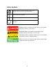
Safety Symbols CAUTION indicates a hazardous situation which, if not avoided, could result in minor or moderate injury. Chassis (earth ground) symbol. On (Power) Off (Power) DANGER indicates a hazardous situation which, if not avoided, will result in death or serious injury.
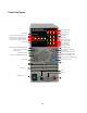
Front Panel layout Set Voltage indicator CC mode indicator Voltage value CV mode indicator OCP indicator Cursor position B or preset B is active Cursor position A or preset A is active OVP indicator Cursor position C or preset C is active Cursor position D or preset D is active Preset mode indicator Keys locked indicator Current value Shift mode indicator Output off indicator Set Current in
Introduction The 9110 and 9111 are unlike conventional power supplies with fixed output ratings. They automatically recalculate voltage/current limits for each setting, forming a constant power, hyperbolic shaped boundary, as illustrated in the diagram below. Any Volt/Amp combination that doesn’t exceed 100W, 60V or 5A (or 180W, 60V or 8A for 9111) can be set.
Features Digitally controlled, mixed linear/switching mode DC power supply 10mV/1mA resolution over the full range Bright, easy to read display Low ripple and noise Very compact size and light weight Output ON/OFF Control High reliability due to OVP, OCP and OTP (over voltage, over current, over temperature) protection CV (Constant Voltage) and CC (Constant Current) operation Store/Recall 100 groups with 4 sets of Volt/Amp memories each 12
Installation Please inspect the instrument mechanically and electrically upon receiving it. Unpack all items from the shipping carton, and check for any obvious signs of physical damage that may have occurred during transportation. Report any damage to the shipping agent immediately. Save the original packing carton for possible future reshipment.
Fuse Replacement Follow the steps below to replace or check the fuse. 1. Locate the fuse box next to the AC input connector in the rear panel. 2. With a small flat blade screwdriver, insert into the fuse box slit to pull and slide out the fuse box as indicated below. 3.
Quick Start Press the Set Voltage D V/A Set Voltage 9110 key to turn the “V” CV CC OVP OCP 100W Multi Range 60V/5A DC Power Supply indicator on. Now you can set the voltage B value. Use the cursor keys A to highlight the desired digit then adjust its value with the knob. In this example the cursor is set to position B and the voltage value can be adjusted in 1V increments.
Cursor Position and Step Size Cursor position Voltage step size Current step size A 1A B 1V 0.1A C 0.1V 0.01A D 0.01V 0.001A Check the Set Voltage and Set Current Value The power supply usually displays the actual voltage and current value. Press Shift twice to check the set value for voltage and current. The display will blink for 3 seconds while displaying the set values.
Once the OCP value is set, press 9110 Key sound C to enter the BEEP mode. Use the knob to turn the key sound ON or OFF. Press C to confirm.
Storing Voltage/Current sets Store up to four sets of voltage/current values to the group number assigned in the previous paragraph. Press Shift followed by the A (Save) key. All 4 cursor LEDs A B C D B C D V/A will blink simultaneously. Press one of the A keys to assign one of the 4 available memory location within this group. Proceed accordingly for the other 3 sets. Preset Mode Press Shift followed by the B (Preset) key.
Specification Output Rating Load Regulation Line Regulation Setting Accuracy Readback Accuracy Ripple Dimensions (WxHxD) AC Input Weight (Approx.
SERVICE INFORMATION Warranty Service: Please go to the support and service section on our website at www.bkprecision.com to obtain a RMA #. Return the product in the original packaging with proof of purchase to the address below. Clearly state on the RMA the performance problem and return any leads, probes, connectors and accessories that you are using with the device. Non-Warranty Service: Please go to the support and service section on our website at www.bkprecision.com to obtain a RMA #.
LIMITED ONE-‐YEAR WARRANTY B&K Precision Corp. warrants to the original purchaser that its products and the component parts thereof, will be free from defects in workmanship and materials for a period of one year from date of purchase. B&K Precision Corp.
22820 Savi Ranch Parkway Yorba Linda, CA 92887 www.bkprecision.com © 2007 -‐ 2014 B&K Precision Corp.