
User Manual
Basic Measurements
27
Shielded
Coble
Optional
Shield
Resistance
Under Test
▲
▲
▲
▲
DC V AC V 2W Freq
Aut o
Tri g
MX+B
Shi ft
Cont Rel
¦¸
Period
dB/m
FastMenu Recall Med Slow Hold
CHOICES
LEVEL ENTER
ESC
LOCAL
%
IDC IAC 4W
Ω
FAST
MED
SLOW
ADRS RMT HOLD TRIG
*
MEM AUTO REL FILT MATH SHIFT
4W
ERR
POWER
T2AL 250V
SENSE
Ω4W
VΩ
LO
HI
!
10A
CATⅡ(300V)
CATⅠ(1000V)
350V
MAX
1000V
MAX
12A
MAX
mA
12A
INPUT
R
5
5492B
1
2
/
Digit Multimeter
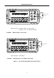
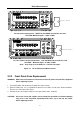
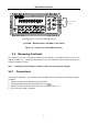
Note: Source current flows from the INPUT HI to INPUT LO terminals
T2AL 250V
SENSE
Ω4W
VΩ
LO
HI
!
10A
CATⅡ(300V)
CATⅠ(1000V)
350V
MAX
1000V
MAX
12A
MAX
mA
12A
INPUT
Shielded
Coble
Optional
Shield
Resistance
Under Test
▲
▲
▲
▲
DC V AC V 2W Freq
Aut o
Tri g
MX+B
Shi ft
Cont Rel
¦¸
Period
dB/m
FastMenu Recall Med Slow Hold
CHOICES
LEVEL
ENTER ESC
LOCAL
%
IDC IAC 4W
Ω
FAST
MED
SLOW
ADRS RMT HOLD TRIG
*
MEM AUTO REL FILT MATH SHIFT
4W
ERR
POWER
R
5
5492B
1
2
/
Digit Multimeter
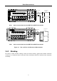
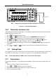
Note: Source current flows from the INPUT HI to INPUT LO terminals
Figure 3-3 Two- and Four- wire Resistance Measurements
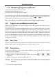
3.4.2 Shielding
To achieve a stable accurate reading, it helps to shield resistances greater than 100 kΩ. Place the
resistance in a shielded enclosure and connect the shield to the INPUT LO terminal of the instrument
electrically.