
User Manual


73
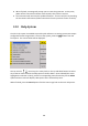
Source
Internal, External
Modulation Waveform
Sine, Square, Ramp, Noise, Arbitrary (2 mHz – 20 kHz)
Phase Deviation
0 – 360 °, 0.1 ° resolution
PWM Modulation
Frequency
500 µHz – 20 kHz
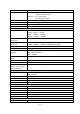
Source
Internal, External
Modulation
Waveform
Sine, Square, Ramp, Noise, Arbitrary (except DC)
External
Modulation
- 6 V to + 6 V (max. width deviation)
Duty Cycle
Modulating
Frequency
2 mHz – 20 kHz
Sweep Characteristics
Waveforms
Sine, Square, Ramp, Pulse, Arbitrary (except DC)
Sweep Shape
Linear or Logarithmic, up or down
Sweep Time
1 ms – 500 s
Sweep Trigger
Internal, External, Manual
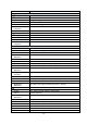
Inputs and Outputs
Output Impedance
50 Ω , High impedance
Sync OUT
TTL compatible
> 50 ns width, not adjustable
50 Ω (typical) output impedance
2 MHz max. frequency
Modulation In
± 6 Vpp for 100% modulation
> 5 kΩ input impedance
Max. voltage input: ± 6 V
External Clock
10 MHz ± 100 Hz, TTL compatible for
external unit synchronization
Ext Trig/Gate/FSK/Burst
TTL compatible
Max. voltage input: ± 6 V
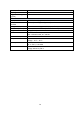
Frequency Counter
Measurement
Frequency, Period, Positive/Negative pulse width, Duty cycle
Measurement Range
(typical)
Single channel: 100 mHz – 200 MHz
Pulse width/Duty cycle: 1 Hz – 10 MHz
Frequency Resolution
6 bits
Voltage range (non-
modulated signal)
DC Coupling
(typical)
DC Offset Range: ± 1.5 VDC
100 mHz to 10 MHz, 450 mV to ± 2.5 V
10 MHz to 50 MHz, 2.5 V to 5 V
50 MHz to 200 MHz, 4.5 V to 5 V
AC Coupling
1 Hz – 100 MHz, 50 mVrms - 5 Vpp
100 MHz – 200 MHz, 100 mVrms – 5 Vpp
Pulse width/Duty cycle
Voltage Range
50 mVrms – 5 Vpp