
Owner's manual
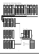
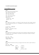

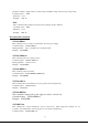

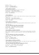


Table Of Contents
31
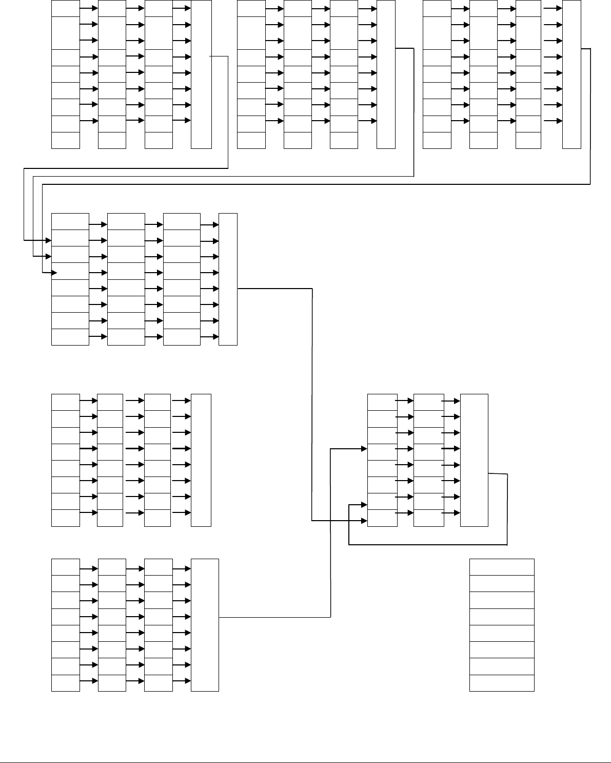
The Structure of the condition register is as followed:
condition event enable condition event enable condition event enable
CAL
CAL
CAL
or
CAL
CAL
CAL
or
CAL
CAL
CAL
or
UNR UNR UNR UNR UNR UNR UNR UNR UN
R
CV CV CV CC CC
CC
CV CV CV
CC CC CC CV CV
CV
CC CC CC
Operation status sub register(channel 1) Operation status sub register(channel 2) Operation status sub register(channel 3)
condition event enable
or
INST1 INST1 INST1
INST2 INST2 INST2
INST3 INST3 INST3
Operation status register
condition event enable event enable
OPC OPC OPC
or
or
QYE QYE QYE
DDE DDE DDE QUES QUES
EXE EXE EXE
CME CME CME ESB ESB
RQS RQS
PON PON PON OPER OPER
Standard event register Status byte register
condition event enable
OV OV OV
or
Lowest bit: 0
OT OT OT
First bit: 1
Second bit: 2
Third bit: 3
Forth bit: 4
Fifth bit: 5
Sixth bit: 6
Highest bit: 7
Quest condition register
Note:
The bit array of each
register is as right
table: