Model: 9115 Multi-Range DC Power Supply PROGRAMMING MANUAL
Table of Contents 1 Remote Operation ........................................................................................4 1.1 Interface Connection ........................................................................................................ 4 RS-232 ..................................................................................................................................... 4 GPIB ......................................................................................................
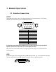
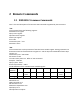
1 Remote Operation 1.1 Interface Connection RS-232 For RS-232 connectivity, refer to the diagram below for pin out information. The RS-232 is labeled in the rear panel and it is a female DB-9 interface. 5 4 9 PIN 1 2 3 4 5 6 7 8 9 3 8 2 7 1 6 Description Transmit Data Receive Data GND - A straight pin-to-pin DB9 female to DB9 male serial cable is required for using the RS-232 interface. Do not use a null modem or crossover DB9 serial cable.
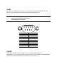
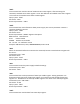
RS-485 For multi-unit configuration and control, the male DB-9 interface labeled RS-485 in the rear panel is used. The below illustrates the connection pins and description. Note: Pin 1 is used as the B pin (+) (non-inverting). Pin 5 is used as the A pin (-) (inverting). SC (reference) pin is not used. 5 4 9 PIN 1 2 3 4 5 6 7 8 9 USBTMC 3 8 2 7 1 6 Description B (+) A (-) - The device is SR1, RL1, and DT1 enabled. It can receive the following request: REN_CONTROL, GO_TO_LOCAL, LOCAL_LOCKOUT.
2 Remote Commands 2.1 IEEE488.2 Common Commands Here’s a list and description of all common SCPI commands supported by the instrument. *CLS This command clears the following registers. Standard event register Query event register Operation event register Status byte register Error code Command syntax: *CLS Parameter: None *ESE This command can set the parameter of standard event enable register.
*ESR? This command can read the value of standard event status register. After executing this command, standard event status register is reset. Bit definition of standard event status register is the same as the standard event status enable register. Query syntax: *ESR? Parameter: None Returned parameter: *IDN? This command can read information about power supply. The returns parameter contains 4 segments divided by comma.
Query syntax: *STB? Parameter: None Returned parameter: *TRG When power supply trigger source is a command from via BUS, this command will give a trigger signal. And its function is the same as “TRIGger” command. Query syntax: *TRG Parameter: None Returned parameter: None *SAV This command can save the current setups of power supply to specified memory.
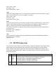
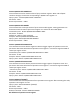
1 3 4 OC OP OT 0 2 3 4 OPC QYE DDE EXE 5 CME 7 PON 2 3 EAV QUES 4 5 6 7 MAV ESB RQS OPER Over current Over power Over temperature Standard event register Operation completed. All the parallel operations are completed. Query error. Output buffer data lost. Instrument memory data loss or self test error Execute error. Command parameter over flow or the operation condition is not consistent Command error. There is syntax or semantic error in the command received.
STATus:QUEStionable:CONDition? This command is used to read the value of query condition register. When a bit of QUES condition changes, the bit value corresponding in QUEST event register is 1. Query syntax:STATus:QUEStionable: CONDition? Parameter: None Returned parameter: STATus:QUEStionable:ENABle This command can set the parameter of quest event enable register. Setting parameter can determine which bit value of quest event register is 1 and the bit will enable QUES.
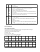
Bit Position Bit Name Bit Weight 7 6 5 4 3 2 1 0 Not used Not used CV CC WTG 16 4 Not used CAL 32 Not used 1 STATus:OPERation:CONDition? This command can read the parameter from the operation condition register. When the parameter of operation condition register changes, the bit corresponding in operation event register is 1.
2.3 SYSTEM Subsystem SYSTem:ERRor? This command is used to read the error code and the error information.
(4) Eeprom failure (5) RST checksum failed (10) RAM selftest failed (40) Flash write failed (41) Flash erase failed (213) RS-232 buffer overrun (216) RS-232 receiver framing (217) RS-232 receiver parity (218) RS-232 receiver overrun (220) Front panel uart overrun (221) Front panel uart framing (222) Front panel uart parity (223) Front panel buffer overrun (224) Front panel timeout (225) Front Crc Check error (226) Front Cmd Error (401) CAL switch prevents (402) CAL password is incorrect (403) CAL not enable
Command syntax: SYSTem:RWLock Parameter: None SYSTem:POSetup This command configures the power on state of the instrument. Command syntax: SYSTem:POSetup RST|SAV0 Parameter: RST|SAV0 Returned parameter: None Query syntax: SYSTem:POSetup? SYSTem:POSetup? Command syntax: SYSTem:POSetup? Parameter: None Returned parameter: RST|SAV0 SYSTem:CLEar This command is used to clear the error codes and information.
This command is used to set the slave machine’s address when communicating through RS485 interface. Command syntax: ADDRess Parameters: 0-31 2.4 TRIGGER Subsystem TRIGger[:IMMediate] This command is used to create a trigger signal. It will give a trigger signal in BUS trigger source mode. The function is the same as command *TRG. Command syntax: TRIGger[:IMMediate] Parameter: None Related commands: *TRG TRIGger:SOURce This command is used to select the trigger source.
[SOURce:]FALL[:LEVel] This command is used to set the voltage falling time of the power supply. Command syntax: [SOURce:] FALL [:LEVel] Unit: s parameter: 0~65.535 Query syntax: [SOURce:] FALL [:LEVel]? Return parameter: 0~65.535 [SOURce:]CURRent[:LEVel][:IMMediate][:AMPLitude] This command is used to set the output current value.
Unit: V| mV| uV Query syntax: [SOURce:]VOLTage[:LEVel]:TRIGgered[:AMPLitude]? Return parameter: [SOURce:]VOLTage:PROTection[:LEVel] This command is used to set the software-voltage protection value.
This command is used to set the lower limitation of the output voltage. Command syntax: [SOURce:]VOLTage:LIMit[:LEVel] Parameter: MIN TO MAX|MIN|MAX|DEF Unit: V| mV| uV Query syntax: [SOURce:]VOLTage:LIMit[:LEVel]? Return parameter: [SOURce:]VOLTage:RANGe This command is used to set the upper limitation of the output voltage.
readings. Command syntax: FETCh:VOLTage? Return parameter: Return parameter unit: V MEASure[:SCALar]:CURRent[:DC]? This command is used to read the actual current. Command syntax: MEASure[:SCALar]:CURRent[:DC]? Parameter: None Return parameter: Return parameter unit: A example: MEAS:CURR? FETCh:CURRent? This command is used to read the current which is in the sample cache. After sending the command, the readings will be sent to the computer. This command does not affect the instrument settings.
2.7 LIST AND SEQUENCE Commands LIST Commands LIST:STATe This command is used to set the state of list mode. Command syntax: LIST:STATe <0|1|ON|OFF> Query syntax: LIST:STATe? Return parameter: 0|1 LIST:RECall This command is used to recall a list file. Command syntax: LIST:RECall Parameter: 1~10 Query syntax: LIST:RECall? Return parameter: 1~10 LIST:EDIT This command is used to select which list file to edit.
Query syntax: LIST:LINK:SEQuence? Return parameter: 0~1023 LIST:SEQuence:REPeat , This command is used to edit the running count of sequence which is linked to the List file. Command syntax: LIST:SEQuence:REPeat, Parameter: Parameter1 represents the sequence number,parameter2 corresponds to the running count of the sequence (1~65535). Query syntax: LIST:SEQuence:REPeat? Return parameter: 0~65535 LIST:SAVe This command is used to save the list file in nonvolatile memory.
Parameter: Parameter1 represents the number of step to be edited.Parameter2 is the current (MIN~MAX). Query syntax: SEQuence:CURRent? Return parameter: MIN~MAX SEQuence:WIDTh This command is used to edit the width of specified step of the sequence file . Command syntax: SEQuence:WIDTh <,NRf> Parameter: Parameter1 represents the number of steps to be edited.Parameter2 is the time width (0.001~65.535). Unit: s Query syntax: SEQuence: WIDTh? Return parameter: 0.001~65.
22820 Savi Ranch Parkway Yorba Linda, CA92887 www.bkprecision.com © 2013, 2014 B&K Precision Corp.