Model: 9115, 9115-AT, 9116 Multi-Range DC Power Supply USER MANUAL
Safety Summary The following safety precautions apply to both operating and maintenance personnel and must be followed during all phases of operation, service, and repair of this instrument. Before applying power to this instrument: • Read and understand the safety and operational information in this manual. • Apply all the listed safety precautions. • Verify that the voltage selector at the line power cord input is set to the correct line voltage.
Do not use this instrument in an electrical environment with a higher category rating than what is specified in this manual for this instrument. You must ensure that each accessory you use with this instrument has a category rating equal to or higher than the instrument's category rating to maintain the instrument's category rating. Failure to do so will lower the category rating of the measuring system. Electrical Power This instrument is intended to be powered from a CATEGORY II mains power environment.
Do not operate the instrument in the presence of flammable gases or vapors, fumes, or finelydivided particulates. The instrument is designed to be used in office-type indoor environments. Do not operate the instrument • In the presence of noxious, corrosive, or flammable fumes, gases, vapors, chemicals, or finely-divided particulates. • In relative humidity conditions outside the instrument's specifications.
Clean the instrument only as instructed Do not clean the instrument, its switches, or its terminals with contact cleaners, abrasives, lubricants, solvents, acids/bases, or other such chemicals. Clean the instrument only with a clean dry lint-free cloth or as instructed in this manual. Not for critical applications This instrument is not authorized for use in contact with the human body or for use as a component in a life-support device or system.
Fuse replacement must be done by qualified service-trained maintenance personnel who are aware of the instrument's fuse requirements and safe replacement procedures. Disconnect the instrument from the power line before replacing fuses. Replace fuses only with new fuses of the fuse types, voltage ratings, and current ratings specified in this manual or on the back of the instrument. Failure to do so may damage the instrument, lead to a safety hazard, or cause a fire.
• • • Do not obstruct cooling air flow to the instrument. Do not place a hot soldering iron on the instrument. Do not pull the instrument with the power cord, connected probe, or connected test lead. Do not move the instrument when a probe is connected to a circuit being tested.
Compliance Statements Disposal of Old Electrical & Electronic Equipment (Applicable in the European Union and other European countries with separate collection systems) This product is subject to Directive 2002/96/EC of the European Parliament and the Council of the European Union on waste electrical and electronic equipment (WEEE), and in jurisdictions adopting that Directive, is marked as being put on the market after August 13, 2005, and should not be disposed of as unsorted municipal waste.
CE Declaration of Conformity The power supply meets the requirements of 2006/95/EC Low Voltage Directive and 2004/108/EC Electromagnetic Compatibility Directive with the following standards.
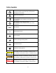
Safety Symbols Refer to the user manual for warning information to avoid hazard or personal injury and prevent damage to instrument. Electric Shock hazard On (Supply). This is the AC mains connect/disconnect switch on the front of the instrument. Off (Supply). This is the AC mains connect/disconnect switch on the front of the instrument.
Table of Contents Safety Summary ...................................................................................................i Compliance Statements ............................................................................................................. vii Safety Symbols ............................................................................................................................ ix 1 General Information ...........................................................................
3.3 Protection Settings ......................................................................................................... 16 Configure Over Voltage Protection (OVP) ............................................................................. 16 Configure Maximum Power Limit ......................................................................................... 17 3.3 SYSTEM Menu ................................................................................................................
5 Troubleshooting Guide ............................................................................... 56 General .................................................................................................................................. 56 Remote Control ..................................................................................................................... 56 6 Specifications .............................................................................................
1 General Information 1.1 Product Overview B&K Precision models 9115, 9115-AT, and 9116 are multi-range single output high power supplies with the capability of producing up to 80 V or 60 A (9115/9115-AT) and 150 V or 30 A (9116) at a maximum power output of 1200 W. With an easy-to-read VFD display, user-friendly controls and a numeric keypad that allows for easy configurations from the front panel.
1.3 Product Dimensions The 9115, 9115-AT, and 9116 power supply’s dimensions (WxHxD) are approximately 414.5 mm x 44.5 mm x 483.2 mm (16.29” x 1.75” x 19.02”). It is designed to fit in a standard 19-inch rackmount and is of 1U size. Note: All dimensions in the figures below are measured in millimeters (mm). Figure 1.1 - Front Panel View for 9115/9115-AT/9116 Figure 1.
1.4 Front Panel Overview 1 2 3 4 16 5 15 14 6 7 13 12 8 9 11 10 Figure 1.3 - Front Panel for 9115/9115-AT/9116 Front Panel Description 1 Power On/Off switch 2 VFD display 3 Voltage adjust knob 4 Current adjust knob 5 6 7 8 9 10 11 12 13 14 Up/Down/Left/Right arrow keys Used to adjust cursor location and selecting menu items. On/Off / Lock button Control the output state or locks the front panel button. Save/Recall button Used to save and recall instrument settings.
15 16 OK Shift key Enables access to secondary functions of some buttons (These functions are labeled in white) OK button (same as Enter button) 4
1.5 Rear Panel Overview 9 10 1 2 3 4 5 6 Figure 1.
1.6 Display Overview OFF CC CV Rmt Addr Error Trig 80.000V 1 Prot * Shift 12.000A 0.0 W VOVP = 85.000 V 2 3 Figure 1.
2 Getting Started Before connecting and powering up the instrument, please review and go through the instructions in this chapter. 2.1 Input Power and Fuse Requirements Input Power Before connecting to an AC outlet or external power source, be sure that the power switch is in the OFF position and verify that the AC power cord, including the extension line, is compatible with the rated voltage/current and that there is sufficient circuit capacity for the power supply.
Connection of this power supply to an AC power source should be made by a qualified electrician or other qualified personnel. Incorrect wiring may damage the power supply or cause a fire hazard Fuse Requirements An AC input fuse is necessary when powering the instrument. Refer to the table below for the fuse requirements. Model All Models Fuse Description 15AT / 250V (6 x 32 mm slow blow ceramic tube fuse) Table 2.
from resistances in the wires. Rear Output Terminal Hex Key Screw 6mm 10mm 10mm 10mm Figure 2.1 - Rear Output Terminal Due to the high current rating of the power supply, proper wire sizes are necessary for safe connectivity and to prevent wires from overheating. Refer to the table below as a reference for proper wire sizes according to the amount of current used for operation: Table 2.2 - Wire Gauge Rating AWG 6 8 10 12 14 16 18 20 22 Imax(A) mΩ/meter 75 1.3 55 2.1 40 3.3 25 5.2 20 8.
System Selftest . . . . .. Self-test Errors The following errors will be displayed if self-test did not complete successfully: Error Message on Display EEPROM FAILURE Config Data Lost Calibration Data Lost FactoryCal.Data Lost MainframeInitialize Lost Description The internal EEPROM is corrupted or damaged. The last operation data within the EEPROM is lost. Calibration data within the EEPROM is lost. Factory calibration data is lost. The system settings within the EEPROM is lost.
Current Check Follow the steps below to check basic current output of the power supply. 1. Turn on the power supply. The display will show the OFF annunciator above the voltage display. Be sure that the output is disabled (the should not be lit when it is off). If not, press to disable output. 2. Short the (+) and (-) output terminals with test leads, shorting bar, or clip. (Refer to “Table 2.2 - Wire Gauge Rating” to select appropriate test leads) 3.
3 Front Panel Operation 3.1 Menu Options All settings and parameters can be configured from the built-in menu system of the power supply. To access the menu, press and press . The menu system is divided into the following sections and organized as follows: SYSTEM CONFIG LIST1 FUNC2 Initialize Power-On Trigger Memory Buzzer Communication ReturnMeter Reset power supply settings to factory default values. Configure power-on state. Configure Trigger.
1. From the normal display, press and press to enter the menu. 2. The selected item will be blinking. Use keys to move through the menu selections. 3. When the desired menu section is blinking, press 4. Below is the display when SYSTEM is selected. SYSTEM MENU In it i al i ze to access its menu settings. Powe r-O n 5. The selected item will be blinking. Use keys to move through the menu items.
Note: To see the changes to the setting voltage, be sure the display is not showing the measured voltage. This can be checked by looking at the If it is not lit, display is showing setting voltage. button backlight. Setting Current Follow the steps below to set the output current: 1. From the normal front panel display, users can use either the current adjust knob or the numeric keypad to enter the setting current. 2.
Vo+ Vs+ Vs- Vo- Figure 3.1 – Local Sense Connection Diagram DO NOT disconnect the wires if remote sense is not used. Doing so will cause erratic behavior and may damage the power supply under certain conditions. Never connect any power source into any of the four terminals at any time during operation. When output is enabled, DO NOT use your hands to touch the terminals or the screws that are designed to tighten wires to the terminals.
Rear Sense Terminal Vo+ Vs+ Vs- Vo- + DUT - Rear Output Terminal Figure 3.2 – Remote Sense Connection Diagram DO NOT at any time disconnect the wires from the Vs+ and Vs- terminals to the DUT while output is enabled (ON). Doing so may damage the power supply and cause unstable output. 3.3 Protection Settings Configure Over Voltage Protection (OVP) Follow the steps below to set the OVP limit: 1. Press the button. The display will show VOVP on the bottom right.
5. To disable OVP at any time, just press will disappear. twice. When it is disabled, the backlight When OVP protection is tripped, the following screen will display: OFF Prot 80.000VOVP 12.000A 0.0 W To clear the trip status, press once. Configure Maximum Power Limit Follow the steps below to set the maximum power limit: 1. Press and then . The display will show Pmax on the bottom right. Use the voltage or current adjust knob or the numeric keypad to enter the maximum power output limit. 2.
OFF Prot 80.000VOPP 12.000A 0.0 W To clear the trip status, press once. 3.3 SYSTEM Menu All setup procedures and settings explained in this section can be accessed from the SYSTEM menu. To access this menu, press and press . When SYSTEM is blinking, press .
Power-On Load Setup External Control Limit Online Setup Output Rst Off 10v-M Vmin = 0.000V, Vmax = 81.000V Off Disabled Configure Power-On State The initial power-On state of the power supply can be configured by following the steps below: 1. From the SYSTEM menu, select Power-On and press 2. There are two options: Rst(Def) – Factory Default. Sav0 – Settings before last power up. 3. Select the settings you want during power up, and press 4. To exit the menu at any time, press . to save changes. twice.
to store settings (0 to 9). The memory group must be selected from the menu first, before settings can be saved within the group. Select Storage Group 1. From the SYSTEM menu, browse and select Memory and press screen will appear. . The following MEMORY Group = 0 2. Use the current adjust knob or the numeric keypad to enter the storage group. Select between 0 – 9. Press to save selection. 3. To exit the menu at any time, press twice. Save Settings 1.
1. Press . Notice the button will be lit and the cursor on the display will disappear. This indicates Recall mode. Instrument settings can only be recalled when the instrument enters this mode. 2. Use the keypad to enter the memory location you want to recall. Enter between 0 to 9. 3. Once entered, the saved settings at the location will be immediately recalled. Note: When in Recall mode, users can recall settings from different locations without having to press additional keys each time.
RS-232 Follow the steps below to configure the power supply for RS-232 operation: 1. From the SYSTEM menu, browse and select Communication and press 2. Select RS-232(Def) and press following display will be shown: . to set to RS-232 for remote communication. The RS232 48 00 , 8 , N , 1 , Add r . . . 3. 4800 is the baudrate; 8 is the data bits; N is the parity; 1 is the stop bit; Addr… is for address. 4. Use to select between each serial settings, and use to change the settings. 5.
GPIB Follow the below instructions to select GPIB interface for remote operation. 1. From the SYSTEM menu, browse and select Communication and press . 2. Select GPIB and press to set to GPIB for remote communication. 3. The display will give a prompt to select an Address. This is the GPIB address to which the power supply will be assigned to. 4. Use the current adjust knob or the numeric keypad to enter an address from 0 – 31. 5.
6. Select Addr… and press . You will be prompted to enter an address. Use current adjust knob or numeric keypad to enter a number between 0 to 31, and then press . 7. For each power supply that you want to control, provide a different address. For example, if you have three power supplies to control, set the first supply to address 1, second supply to address 2, and third supply to address 3. If two or more supplies have the same address, the RS485 protocols will create communication errors. 8.
Load Setup Option The power supply has an internal dummy load that can be enabled to increase the speed of the voltage fall time for high speed test applications. The effectiveness of this function is dependent on the DUT (device under test) and may or may not be useful for some applications. This feature should only be used with caution, as it is not designed for all applications. DO NOT enable this function for applications such as connecting devices for battery charging or powering electric motors.
1. From the CONFIG menu, browse and select Ext-Ctrl and press screen will display: Ext – Ctrl Setup 1 0v -M 10v /10 k- P V- P . The following Of f 2. Select 10v-M or 5v-M so that it is blinking. Use the keys to change between 10vM and 5v-M. – 0 – 5 V scale is used for monitoring 0 – 100% of output. 10v-M – 0 – 10 V scale is used for monitoring 0 – 100% of output. 3. Press 4. Press when finished making the selection. several times to exit the menu.
3. Press 4. Press when finished making the selection. several times to exit the menu. Select Source Type For external voltage and current programming of the output, users can configure the power supply to be controlled with external DC voltages or resistances. Follow the instructions below to select the source type. 1. From the CONFIG menu, browse and select Ext-Ctrl and press screen will display: Ext – Ctrl Setup 1 0v -M 10v /10 k- P V- P . The following Of f 2.
2. Select Off and press . This will disable external analog control. To enable, select any of the three other menu items and press 3. When finished, press after selection. several times to exit the menu. Pin Assignment Below are the pin assignments of the analog interface. Figure 3.
The output state of the power supply can be controlled by EXT_ON (pin 14) and DGND (pin 1). Output ON State - Pin 14 and Pin 1 are connected/shorted together. Output OFF State - Pin 14 and Pin 1 are opened and not connected together. Emergency Shut Off In the case where an emergency shut off to the output of the power supply is required, SHUT_OFF (pin 15) and DGND (pin 1) is used. To shut off, connect/short Pin 15 and Pin 1 together.
The voltage and current output can be monitored using VMON (pin 23) and Ground (pin 11) for voltage and IMON (pin 24) and Ground (pin 12) for current. Follow the instructions in the previous sections for configuration of the voltage scale to use for monitoring. The scale can be selected between 0 – 10 VDC or 0 – 5 VDC to reflect 0 – 100% of voltage or current output. Reference Voltage A 10 VDC reference output is available on REF_10V (pin 21) and Ground (pin 9).
. The screen will return to the CONFIG menu. 5. When finished, press 6. Press several times to exit the menu. Parallel/Series Connection More than one unit of the same model can be connected in a parallel or series configuration. Table 3.2 below shows the total number of units that can be connected in each configuration. The power supplies can be set up in master/slave mode so that the master unit can control all other power supplies in the parallel or series connection.
For safety, always turn OFF the power supplies before connecting or disconnecting wires to the output terminal. For parallel connection: Connect each power supplies’ positive (+) terminals together. Do the same for the negative (-) terminals. For series connection: Connect one power supply’s positive (+) terminal to the negative (-) terminal of another. Do the same for all the power supplies. Then, connect all of the power supplies’ Pin 1 of the RS-485 interface together. Do the same for Pin 5.
- + DUT + - Figure 3.5 - Master/Slave Series Connection Diagram Master/Slave Setup Only one power supply has to be configured as a Master. The rest must be configured as Slave. Up to 3 units can be configured in total. Note: Configure Slave power supplies FIRST, and configure the Master power supply LAST. For remote or front panel operation, only control the Master power supply.
3. Press the key to select Slave or Master. Use the keys to select between the two options. Select Master to set the power supply as a master, or select Slave to set the power supply as a slave. Always set the Slave supplies first and Master supply last. 4. Press the key to select Addr…. Press and the display will prompt to enter an address. Use the numeric keypad to enter an Address, which must be different than all other power supplies that you want to connect together in parallel.
There are three separate configurations to set up for programming and running a sequence (in order): 1. Configure Sequence Parameters 2. Configure Program (List) 3. Recall and Run Program Note: These configurations must be set up in order. The following sections will go into the details of setting up all three configurations. Note: It is recommended that the Trigger Source be configured prior to setting up the configurations.
V 3 2 1 S 1s 2s 3s 3s 4s Figure 3.7 - Program Sequence Example 1. Access the main menu by pressing 2. Use the press and the key to select LIST (FUNC. then press . twice for model 9115-AT) and . The below screen will display: 3. Use the key to select EditSeq and press . The display will say EDIT SEQ and an entry for Seq Name: is displayed. 4. Use the current adjust knob or the numeric keypad to select any number between 1 – 10 to edit its sequence. Press .
Pressing the same number will change the “Y” back to the corresponding number. For example, if you want to configure and store a sequence with steps 1, 4, 6, and 8, press 1, 4, 6, and 8 on the numeric keypad so that the following will display: SEQ A c ti ve Step: 09Y7 Y5Y32Y 7. For this example, steps 1, 2, 3, 4, and 5 will be used, so use the numeric keypad and press 1, 2, 3, 4, and 5 until it displays: SEQ A c ti ve Step: 09876 YYYY Y 8. Once set, press .
EDIT SEQ WIDTH S eq Step 1 Width = 1. 000 s 12. Enter the width, which is the time to hold the voltage and current setting configured in the previous steps. Enter 1.000 (for 1 second). Press display: . Now, the following will EDIT SEQ SLOPE S eq Step 1 Sl ope = 0.005 s 13. Enter the slope, which defines the voltage slew rate (transition time between steps) for step 1. Enter 0.005. Press . 14.
The sequence(s) to execute and run can be selected, as well as its repetitiveness. This means multiple sequences can be run one after another. With 10 steps per sequence and up to 10 sequences configured, a program can run with a maximum of 100 steps. As an example, take the sequence illustrated in the previous section as sequence #1, and sequence #2 to run after sequence #1.
EDIT LIST REPEAT L ist Re pe at = 1 4. The display prompts the user to enter the number of times to repeat the program (list). For this example, enter 5 with the numeric keypad and then press . Note: The maximum number of repeat times is 65535 times. 5. The next display will show the following: FILE A c ti ve Seq : 0 987654 321 6. This is similar to step 5 and 6 in the previous section for Configure Sequence Parameters.
9. The display prompts the user to enter the number of times to repeat sequence #1 as part of the program (list). In this example, use the current adjust knob or the numeric keypad to enter 2. Press and the same prompt will immediately follow for sequence #2. Enter 3 and then press . 10. Now it will display the following to confirm saving the program (list). SAVE LIST No 11. Press Yes key to select Yes and press to save the program (list) into memory. 12.
2. Now, press twice to exit the menu. The following will display: OFF Trig 0.000V 0.000A LIST 0.0 W 3. If the display is showing the measured voltage and current value, the should be lit and display should show 0.000V and 0.000A. backlight 4. Now, press the key to enable (ON) the output. 5. If the Trigger Source configured in section 3.3 is set to Manual (Def), then the front panel trigger key can be used to initiate the program. Press 6.
Figure 3.8 – Test Pulse waveform (DIN 40839) Table 3.4 – Parameters for test pulse Follow the steps below to set up the DIN40839 function: 1. Access the main menu by pressing and the 2. Use the key to select FUNC. and press 3. Use the key to select DIN40839 and press 43 . . .
DIN40839 12 V Of f 4. While 12V or 24V is flashing, use keys to toggle between the two options. Set to 12V for the 12V test function and 24V for the 24V test function. 5. Use the key to select Off/On and use keys to toggle between the two options. Choose On to be able to run the function. 6. Once both parameters are set, press to confirm the changed settings and press twice to exit the menu.
Figure 3.9 – Short voltage drop waveform Figure 3.
Figure 3.11 – Starting profile waveform Table 3.
Table 3.6 – Starting profile values for 24 V system devices Short voltage drop Follow the steps below to set up the ISO16750-2 for Short voltage drop function: 1. Access the main menu by pressing and the 2. Use the key to select FUNC. and press 3. Use the key to select ISO16750-2 and press . . . The screen below will display: ISO16750-2 profile S ho rt vol tage d rop 4. While Short voltage drop is flashing, press to access that option.
0.000V 0.0 W Trig 0.000A S ho rt vol tage d rop 7. To enable the Short voltage drop function, press the key, on the front panel. The proper voltage (12V or 24V) should be metered on the front panel display. 8. To run Short voltage drop function press and to trigger the test to run. 9. Repeat step 8 to trigger the function to run as many times as needed. Profile for reset Follow the steps below to set up the ISO16750-2 Profile for the reset test function: 1. Access the main menu by pressing 2.
Trig 0.000V 0.0 W 0.000A P rof il e for reset 8. To enable the Profile reset test function, press the key, on the front panel. The proper voltage selected should be metered on the front panel display. 9. To run the Profile reset test function press and to trigger the test to run. Please be aware this test does run for 340 seconds (See profile reset test figure above).
10. Once both parameters are set, press to confirm the changed settings and press several times to exit the menu. If the Starting profile function was setup properly, the Trig indicator will be highlighted and Starting profile will be shown on the front panel, shown below. 0.000V Trig 0.0 W 0.000A S tart in g p ro fi le 11. To enable the Short voltage drop function, press the key, on the front panel. The proper voltage (12V or 24V) should be metered on the front panel display. 12.
10V 5V 1V 5 seconds 10 seconds Figure 3.12 – Voltage Slope Waveform Example Follow the steps below to configure the voltage slope to simulate the voltage output signal above. 1. Press and . The screen below will be displayed. OFF 80.000V 12.000A Trise = 0.0 W 0.000s 2. Trise is the rising edge time for an output voltage transition. Use the numeric keypad or the current adjust knob and enter 5.000 s (5 seconds). 3. Press and Tfall will be displayed.
9. When the supply has reached 10 V, use the numeric keypad and enter 1 V. Press and observe the output voltage slowly ramping down to 1 V over a span of 10 seconds. 3.8 Key Lock The front panel keys can be locked to prevent unwanted changes to output settings and power supply configurations. Follow the steps below to enable/disable key lock. 1. Press and . A * indicator will light up on the display, indicating that the front panel keys are lock.
4 Remote Operation 4.1 Interface Connection RS-232 For RS-232 connectivity, refer to the diagram below for pinout information. The RS-232 is labeled in the rear panel and it is a female DB-9 interface. 5 4 9 3 8 PIN 1 2 3 4 5 6 7 8 9 2 7 1 6 Description Transmit Data Receive Data GND - A straight pin-to-pin DB9 female to DB9 male serial cable is required for using the RS-232 interface. Do not use a null modem or crossover DB9 serial cable.
RS-485 For multi-unit configuration and control, the male DB-9 interface labeled RS-485 in the rear panel is used. The figure below illustrates the connection pins and description. Note: Pin 1 is used as the A pin (-) (non-inverting). Pin 5 is used as the B pin (+) (inverting). SC (reference) pin is not used. 5 4 9 3 8 PIN 1 2 3 4 5 6 7 8 9 2 7 1 6 Description A (-) B (+) - USBTMC The device is SR1, RL1, and DT1 enabled.
4.2 Remote Commands The instrument supports some SCPI commands and some instrument specific commands. These commands enable a computer to remotely communicate and control the power supply over any of the supported remote interfaces: USBTMC, RS-232, GPIB, and RS-485. Refer to the programming manual for details, which can be downloaded from www.bkprecision.com.
5 Troubleshooting Guide Below are some frequently asked questions and answers. Please check if any apply to your power supply before contacting B&K Precision. General Q: I cannot power up the power supply. - Check that the power cord is securely connected to the AC input and there is live power from your electrical AC outlet. - Verify that the AC power coming from the mains have the correct voltage. The power supply can accept a specific range of AC input voltages. Refer to section “2.1”.
6 Specifications Note: All specifications apply to the unit after a temperature stabilization time of 15 minutes over an ambient temperature range of 23 °C ± 5 °C. Specifications are subject to change without notice. Environmental Conditions: This power supply is designed for indoor use and operated with maximum relative humidity of 95%.
7 Calibration We recommend a calibration interval of once per year to ensure that the power supply meets specifications.
SERVICE INFORMATION Warranty Service: Please go to the support and service section on our website at www.bkprecision.com to obtain a RMA #. Return the product in the original packaging with proof of purchase to the address below. Clearly state on the RMA the performance problem and return any leads, probes, connectors and accessories that you are using with the device. Non-Warranty Service: Please go to the support and service section on our website at www.bkprecision.com to obtain a RMA #.
LIMITED ONE-YEAR WARRANTY B&K Precision Corp. warrants to the original purchaser that its products and the component parts thereof, will be free from defects in workmanship and materials for a period of one year from date of purchase. B&K Precision Corp. will, without charge, repair or replace, at its option, defective product or component parts. Returned product must be accompanied by proof of the purchase date in the form of a sales receipt.
22820 Savi Ranch Parkway Yorba Linda, CA 92887 www.bkprecision.com © 2014 B&K Precision Corp.