USER MANUAL 8500 SERIES DC ELECTRONIC LOADS Models 8500, 8502, 8510, 8512, 8514, 8518, 8520, 8522, 8524 & 8526
Safety The following general safety precautions must be observed during all phases of operation of this instrument. Failure to comply with these precautions or with specific warnings elsewhere in this manual violates safety standards of design, manufacture, and intended use of the instrument. B&K Precision assumes no liability for the customer’s failure to comply with these requirements. Verify that all safety precautions are taken. Note the instrument's external markings described under "Safety Symbols".
Table of Contents Safety...................................................................................................................................................... 2 Safety Symbols................................................................................................................................... 2 Notation................................................................................................................................................... 5 Quick reference..............
Voltage threshold operation.............................................................................................................. 42 Passwords........................................................................................................................................ 42 Protection features............................................................................................................................ 43 Over Voltage protection....................................................
Notation I-set Represents a key on the front panel. Note that some of these may be accessed in combination with the Shift key. OFF Annunciator, value, or message shown on the vacuum fluorescent display.
Quick reference Model numbers covered by this document The B&K Precision DC Loads covered by this manual are: ● ● ● ● ● ● ● ● ● ● 8500 8502 8510 8512 8514 8518 8520 8522 8524 8526 Unless otherwise noted, this document will refer to all of these instruments as the DC Load. Instrument differences, where appropriate, will be noted. Options and accessories The items included with the instrument are: 1. Power cord 2. User manual 3.
whose resistance doesn't change as a function of current or voltage). The DC Load can present dynamically changing loads to the DC source with millisecond switching times. The DC Load can be remotely programmed via a serial interface (RS-232 or USB). Versatile triggering options allow the dynamic load behavior to be synchronized with other events. A battery test mode is provided that will measure the ampere*hour (A*hr) characteristic of a battery.
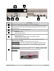
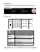
2 1 3 4 5 6 Button Function(s) 1 16-character display shows voltage and current measurements. Rotary knob. Turn to adjust a setting value. Press in to toggle between setting the currently-selected mode's value and reading the voltage and current, as shown in the above picture. Power switch to turn the instrument on or off. Numeric keypad: Numeric entry keys. Secondary key functions. Keypad: Enable/disable input. Set up the current, voltage, power, and resistance modes.
Standard display The standard display for the instrument is the voltage and current at the instrument's terminals. You may press the △ or ▽ keys to see the instantaneous power and the mode's parameter setting.
Shift + Menu Shift + Short Shift + Tran Shift + Trigger Shift + Battery Shift + S-Tran On/Off Shift △ ▽ 0 to 9 • Esc Enter Enter the instrument's menu system. Turn short circuit on or off. Start or stop transient condition. Causes an immediate trigger. Turn on or off battery testing function (measures battery capacity in ampere*hours). Set transient condition parameters. Turns DC Load ON or OFF (OFF is high impedance state).
not covered by warranty. Line voltage selection switch (110 VAC or *220 VAC) *For models 8524 and 8526, the line voltage switch is not usable and does not allow for 220VAC operation. Do not connect them directly into a 220V line. For 220V operation, please order model 8524-220V or 8526-220V. 4 Power Requirements All of the models, except for models 8524 and 8526, can accept 110V or 220V line input. To switch between the two line voltage inputs: 1.
Annunciator LIMIT ERROR LINK RMT SHIFT LOCK Meaning Not used. An error has occurred. The instrument is communicating with an IT-E131 or IT-E132 communications adapter. This annunciator will stay lit for approximately 3 seconds after the last remote communication with the DC Load. Instrument is in the remote state. The only active key is the Local key. This is set with the 0x20 remote command (see the Remote programming section). The Shift key has been pressed. The keyboard is locked by a password.
Lvl Menu item Function better voltage and/or current resolution. Press Shift + △ or Shift + ▽ to toggle resolutions. 3 2 3 3 2 3 3 OFF REMOTE SENSE ON OFF ADC UPDATE RATE HIGH TRIGGER SOURCE 3 IMMEDIATE 3 EXTERNAL 3 2 BUS CONNECT MODE 3 MAXTIPLEXING 3 SEPARATE 3 3 3 3 2 BAUDRATE SET Remote sensing is off. Set the rate at which the display is updated. How the instrument is triggered. Triggered from the Shift + Trigger key.
Lvl Menu item 2 MAX VOLTAGE SET 2 VOLTAGE ON SET 2 VOLTAGE OFF SET 2 1 2 3 EXIT LIST SET MODE SET FIXED MODE 3 LIST MODE 2 3 CALL LIST FILE RECALL N 2 EDIT LIST FILE 3 4 4 3 4 4 3 4 4 3 4 4 2 3 2 CURRENT LIST ONCE REPEAT VOLTAGE LIST ONCE REPEAT POWER LIST ONCE REPEAT RESISTANCE LIST ONCE REPEAT CALL TEST FILE RECALL N EDIT TEST FILE 2 LIST STORE MODE 3 3 3 3 2 1 8 X 120 STEPS 4 X 250 STEPS 2 X 500 STEPS 1 X 1000 STEPS EXIT LOAD ON TIMER 8500 DC Load Series Function the maximum power
Lvl 2 Menu item TIMER STATE 3 ON 3 OFF 2 TIMER SET 2 1 Function EXIT EXIT 8500 DC Load Series When the load timer is enabled by this menu element, the load is turned on when the On/Off key is pressed. After the set time period has elapsed, the load is turned off. When the load is turned on via the On/Off key, the load stays ON indefinitely. Set the time period from 1 to 60000 s for the load to be on. Return to prior menu level. Return to standard display.
Specifications Models 8500 & 8502 (300 W) Parameter 8500 0 to 120 V 1 mA to 30 A Voltage Current Power Input rating 8502 0 to 500 V 1 mA to 15 A 300 W 8500/8502 common characteristics Range Accuracy 8500 8502 0.1-18 V ±(0.05%+0.02% FS) 0.1 – 120 V 0.1 – 500 V ±(0.05%+0.025% FS) 0–3A 0–3A ±(0.1%+0.1% FS) 0 – 30 A 0 – 15 A ±(0.2%+0.15% FS) 0–3A 0–3A ±(0.1% + 0.1% FS) 8500: ±(0.2%+0.15% FS) 0 – 30 A 0 – 15 A 8502: ±(0.2%+0.3% FS) 0-18 V ±(0.02% + 0.02% FS) 0-120 V 0 – 500 V ±(0.02% + 0.
Models 8520/8522/8524/8526 (2400W & 5000W) Parameter Input rating Parameter CV Mode Regulation CC Mode Regulation Current Measurement Voltage Measurement 8520 Voltage Current Power 8522 0 – 120 V 0 – 500 V 0 – 240 A 0 – 120 A 2400 W 8524 0 – 60 V 0 – 240 A 8526 0 – 500 V 0 – 120 A 5000 W 8520/8522/8524/8526 common characteristics Range Accuracy 8520 8522 8524 8526 0.1-18 V ±(0.05%+0.02% FS) 0.1 V to Vmax ±(0.05%+0.025% FS) 0-24 A 0-12 A 0-24 A 0-12 A ±(0.1%+0.1% FS) 0 – max Current ±(0.2%+0.
Parameter Specification Humidity ≤ 95% relative humidity, non-condensing Altitude ≤ 2000 m AC Input *220 ACV ± 10%,47~63 Hz 110 ACV ± 10%,47~63 Hz Operating temperature 0 – 40 ºC Storage temperature -10 – 60 ºC *For 220V operation on models 8524 and 8526, please order model 8524-220V and 8526-220V respectively.
The curved portion is where the dissipated power is at the rated power of the instrument (and is actually a hyperbolic shape). When you use the menu to set lower-than-maximum power or current, the operating region may look like the following: Note the gap between the operating region and the current axis for lower voltages. More detail is described in the following section.
Slew rate 8500 DC Load Series Version: 030614 Page 20 of 77
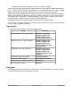
The slew rate for each DC load varies from model to model. The variations are also dependent on the different regions measured for each individual load. In general, the slew rate for low current transitions, say 0 to 0.5 A, is significantly lower than slew rate for current transitions from 30 to 70 A. The provided table below indicates measured slew rates based on the maximum range of current transition of the models are capable of.
8500 DC Load Series Model Slew rate 8500 0.5A / S 8502 0.5A / S 8510 1A/ S 8512 0.
Glossary △ Up arrow key. Used to scroll through the menu or cause the temporary display of the alternate standard display. ▽ Down arrow key. Used to scroll through the menu or cause the temporary display of the alternate standard display. A Value for first setting of transient mode. B Value for second setting of transient mode. Battery Select battery testing mode. See Battery test section. CC Constant current Condition Steady state, transient, or dynamic.
R-set Configure the instrument for constant resistance mode. Recall Recall instrument state from non-volatile memory. Remote sensing Allows the instrument to measure the load power properly in case of large currents by sensing the voltage at the source, rather than at the instrument's terminals. This removes the effect of the resistance of long leads. S-Tran Set parameters (A, B, and transition times) for transient mode.
Installation Inspection Items you should have received When you open the box containing the instrument, you should find the following items: 1. 2. 3. 4. 5. 6. The DC Load instrument Power cord User manual Installation CD with application software PV8500 TTL to RS-232 serial converter IT-E131 Calibration report Instrument location This instrument is intended for indoor use in a pollution degree 2 environment. Please refer to the specifications table for the allowable environment operating limits.
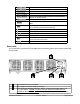
Models 8510, 8512, 8514 & 8518 Models 8520, 8522 8500 DC Load Series Version: 030614 Page 26 of 77
Models 8524 & 8526 Unit (mm) 8500 DC Load Series Version: 030614 Page 27 of 77
Model number Dimensions in mm Mass in kg 8500 215W×88H×355D 5.2 8502 215W×88H×355D 5.2 8510 429W×88H×355D 14 8512 429W×88H×355D 14 8514 429W×88H×355D 14 8518 429W×88H×355D 14 8520 444W×180H×539D 30 8522 444W×180H×539D 30 8524 444W×357H×539D 67 8526 490W×357H×539D 67 Bench operation The 8500 DC Load is provided with a carrying handle. The following pictures demonstrate various ways to use the handle. The handle may be removed if desired.
First turn-on checkout Ensure that the line voltage selector switch on the back panel is set to match your line voltage. Failure to do so could result in damage to the instrument. CAUTION Note: For models 8524 and 8526, the line voltage switch is not usable and does not allow for 220VAC operation. Do not connect them directly into a 220V line. For 220V operation, please order model 8524-220V or 8526-220V.
Press the V-set button (you may have to press it twice). Note the load is turned off. Set the power supply to 10V and the supply's current to a very low level, e.g. 0.1 A. Set the DC Load voltage level well below the supply voltage level, e.g. 1 V. Press the On/Off key. Verify the proper voltage level (1 V) is shown on the display. Press the △ or ▽ keys to see the power being dissipated. Press the P-set button (you may have to press it twice). Note the load is turned off. Set the power level to 0.1 watt.
Examples of the three conditions of operation are illustrated in the following diagram: Steady state B Transient A Dynamic Repeat Time Power-on state The default power-on instrument state is to not remember the instrument mode settings before the last power-down.
Key Display Esc Standard voltage/current display Constant current mode In constant current mode, the DC load will sink a constant current, regardless of the voltage at its terminals. To set up the DC Load to operate in constant current mode and in the steady state condition, use the following keystrokes: Key Display I-set If you press this key after powering up and there is no currentlystored constant current value, you'll be prompted for the desired current level.
In constant power mode, the DC load will cause a constant power to be dissipated in the load. To set up the DC Load to operate in constant power mode and in the steady state condition, use the following keystrokes: Key Display P-set If you press this key after powering up and there is no currentlystored constant power value, you'll be prompted for the desired power level. If there was a power value already stored, it will be momentarily displayed and the instrument will be in CW mode.
Key Display Shift + Menu :CONFIG △ △ :LOAD ON TIMER Enter :TIMER STATE Enter Use arrow keys to set to :ON. ▽ :TIMER SET Enter TIMER=XXXXXS Enter desired time interval. Valid values are 1 to 60000 seconds (1000 minutes). Enter :TIMER SET Esc Esc Standard display Now, when you turn a load on, it will stay on for the designated time, then turn off. To turn off timed operation, enter the menu :CONFIG:LOAD ON TIMER:TIMER STATE and set it to :OFF.
The battery test feature measures the time it takes for a battery voltage to drop to a specified value while drawing a constant current from the battery. When the voltage at the DC Load's terminals reaches the specified voltage, the test is ended and the integrated current (i.e., charge supplied by the battery) in ampere*hours (A*hrs) of the battery is calculated and displayed. To run a battery test, follow these steps: Key presses Display I-set, enter current value with numerical keys, then press Enter.
Keys Display I-set Standard display of voltage and current (or, you'll be asked to enter a current value). Shift + S-Tran LEVEL A= X.XXXA You are being prompted for the first current value. Press the 5 key for 5 A. Enter Enters the 5 A value, then displays WIDTH A = X.XMS. You're being prompted for the duration of the 5 A load -- press the 3 key for 3 ms. Enter Enters the 3 ms value, then displays LEVEL B= X.XXXA. You are being prompted for the second current value.
Keys Display this width is ignored, so enter any convenient value. Enter Displays LEVEL B= X.XXXA. You are being prompted for the second current value. Press the 1 and 0 keys to enter 10 A. Enter Enters the 10 A value, then displays WIDTH B = X.XMS. You're being prompted for the duration of the 10 A load -- press the 1 and 0 key for 10 ms. Enter Enters the 10 ms duration, then displays :CONTINUOUS, :PULSE, or :TOGGLED. Use the △ or ▽ arrow keys to display :PULSE.
Keys Display prompted for the duration of the 5 A load. In the toggled mode of operation, this width is ignored, so enter any convenient value. Enter Displays LEVEL B= X.XXXA. You are being prompted for the second current value. Press the 1 and 0 keys to enter 10 A. Enter Enters the 10 A value, then displays WIDTH B = X.XMS. You're being prompted for the duration of the 10 A load. .
Trigger 0 1 2 3 4 5 List count=1 List count=2 List sequence This list is characterized by the following current/duration pairs Current, A Duration, ms Between times 3 0 2 0 6 1000 800 500 300 500 0 and 1 1 and 2 2 and 3 3 and 4 4 and 5 This list has 5 steps, located at the transitions 1 through 5. The first duration, 1000 ms, occurs after the triggered event. Subsequent durations are from the previous transition to the current transition.
Keys Esc Esc Display Standard display First, press the On/Off key. The load will sink the current that is stored as the CC mode parameter (set it to 0 A if you don't want an initial current). Then press Shift + Trigger to have the list start executing. Should you wish to have the list only execute once after the trigger, you can edit the list to use :ONCE instead of :REPEAT.
Keys Display Enter MIN 1= 5.80V We want the minimum voltage read back to be at least 4.4 V. 4.4 Enter MAX 1= 6.15V The maximum value we'll allow is 4.6 V. 4.6 Enter DELAY 1= 1.0 This delay time is how long to wait before making the readback measurement. If you set it to 25.5 seconds, the test will halt at this point, requiring you to press Shift + Trigger to continue the test. We'll use 1 second. 1 Enter CONST CURRENT We're being prompted for the mode to use for the next step.
Keys Display another test run or press Esc to return to the normal display. Esc Return to the normal display. Triggering Triggering is used with the transient and dynamic conditions to allow synchronization of the DC Load's behavior with other events. There are three types of triggers you may use (set in the CONFIG:TRIGGER SOURCE menu): Trigger Type Explanation IMMEDIATE An immediate trigger is created by pressing Shift + Trigger on the front panel keys.
Shift + A Shift + B Shift + Short Shift + Tran Shift + Trigger On/Off To remove the password, enter the menu CONFIG:KEY LOCK SET and do not press any number keys, then press Enter. Protection features To protect external hardware when using the DC Load, you can set the maximum allowed values for current, voltage, and power. These settings will override any settings subsequently made from the front panel using the I-set, V-set, P-set, or R-set keys.
flashing current value. Over Power protection If the input power exceeds the power limit in the normal operation mode, the DC load will enter the over power protection state. The display will show CW. If the input power exceeds the limit when in transition mode or list mode, the buzzer will sound and the display will flash the current value and voltage value.
The following shows a wiring diagram for remote sensing: Example: A power supply is connected to the DC load with 72.5 cm of 20-gauge solid copper wires. The constant current i set to 5 A. The power supply's output meter reads 27.0 V and the DC Load's voltage display reads 26.71 V with a power dissipation of 133.70 W. This is without remote sensing enabled. With remote sensing turned on and the remote sensing terminals connected to the power supply output terminals, the DC Load reads 26.
Remote operation Communication cables The DC Load has a DB9 connector on the rear panel that allows remote communication. WARNING Do not connect the DC Load's DB9 connector to a standard RS-232 instrument. Doing so may damage the instrument, as the instrument requires TTL logic signals, not standard RS-232 voltages. Two adapters are available to perform the correct level shifting. RS232 to TTL serial converter cable IT-E131 Connect the INSTRUMENT side of the adapter to the DC load DB9 connector.
This COM port can then be accessed as if it were a regular RS-232 port. The LEDs in the adapter will blink when information is being sent through the adapter. This is a good way to tell if your communication link is active. RS-232 settings In order for the computer to communicate with the DC Load, both must be set to the same RS-232 settings. These communication settings are: 1. Baud rate must be one of 4800, 9600, 19200, or 38400. 2. 8 data bits. 3. One stop bit. 4. No parity.
The checksum number is the arithmetic sum of each of the bytes modulo 256. Status packets When you send a command that does not cause the DC Load to send requested information back to you, you will receive a status packet back.
if i % 10 == 0 and i != 0: print print header, if i % 5 == 0: print " ", s = "%02x" % ord(bytes[i]) if s == "00": s = chr(250)*2 print s, print def CalculateChecksum(cmd): assert((len(cmd) == length_packet - 1) or (len(cmd) == length_packet)) checksum = 0 for i in xrange(length_packet - 1): checksum += ord(cmd[i]) checksum %= 256 return checksum def main(): port = 3 # COM4 for my computer baudrate = 38400 sp = serial.
You can download a complete python program along with detailed documentation from our website at www.bkprecision.com Here are the printed results when the above script is ran: Set to remote command: aa ·· 20 01 ·· ·· ·· ·· ·· ·· ·· ·· ·· ·· ·· Response: aa ·· 12 80 ·· ·· ·· ·· ·· ·· ·· ·· ·· ·· ·· ·· ·· ·· ·· ·· ·· ·· ·· ·· ·· cb ·· ·· ·· ·· ·· ·· ·· ·· ·· ·· 3c The · characters represent the bytes with a value of 0x00. This makes it easier to see the nonzero bytes in the string.
Chapter organization The remainder of this chapter contains a reference on the syntax of DC Load commands and some example programs. The Summary of commands section is a list of the commands, but without details. The Command details section explains how to use each command. Summary of commands The Byte values in the following table are used to identify the commands to be sent in the command packet (byte 2).
Command Group Byte Action 0x3A Select the list operation (CC/CV/CW/CR) 0x3B Read the list operation (CC/CV/CW/CR) 0x3C Set how lists repeat (ONCE or REPEAT) 0x3D Read how lists repeat 0x3E Set the number of list steps 0x3F Read the number of list steps 0x40 Set one of the step's current and time values 0x41 Read one of the step's current and time values 0x42 Set one of the step's voltage and time values List operations 0x43 Read one of the step's voltage and time values 0x44 Set one of the step's power
Command Group Byte Action 0x5C Recall DC Load's settings 0x5D Select FIXED/SHORT/TRAN/LIST/BATTERY function Function 0x5E Get function type (FIXED/SHORT/TRAN/LIST/BATTERY) Read display values 0x5F Read input voltage, current, power and relative state 0x60 Enter instrument calibration state 0x61 Get the instrument calibration state 0x62 Set voltage calibration point index 0x63 Send the actual voltage to the calibration program Calibration 0x64 Set current calibration point index 0x65 Send the actual
Most significant two bytes, least significant byte Most significant two bytes, most significant byte Higher low byte Higher high byte As an example, for the integer 0x23A749F5, we'd have 1st byte 2nd byte 3rd byte 4th byte 0xF5 Lower low byte 0x49 Lower high byte 0xA7 Higher low byte 0x23 Higher high byte 0x12 Indicates a return packet for a command sent to the DC Load Byte offset 3 4-24 Meaning Status byte (i.e., status of last command sent to DC Load).
Byte offset Meaning 5 Upper low byte of maximum voltage. 6 Upper high byte of maximum voltage. 7-24 Reserved Example: Suppose you want to set the maximum voltage to 16.23V. Since 1 represents 1mV, therefore 16.23V translates to 16,230 in decimal. With 4 bytes in Hex, that would be 0x0003F66. Since the bytes are ordered in little-endian format, 0x66 would be the 3rd byte, 0x3F the 4th byte, 0x00 as 5th byte, and 0x00 as the 6th byte.
Byte offset Meaning 5 Upper low byte of maximum current. 6 Upper high byte of maximum current. 7-24 Reserved 0x26 Set the maximum power allowed Byte offset Meaning 3 Lower low byte of maximum power. 1 represents 1 mW. 4 Lower high byte of maximum power. 5 Upper low byte of maximum power. 6 Upper high byte of maximum power. 7-24 Reserved Example: Suppose you want to set the maximum power to 213.45W. Since 1 represents 1mW, 213.45W translates to 213,450 in decimal.
Byte offset 3 4-24 Meaning Mode: 0 is CC 1 is CV 2 is CW 3 is CR Reserved 0x2A Set CC mode current Byte offset Meaning 3 Lower low byte of current. 1 represents 0.1 mA. 4 Lower high byte of current. 5 Upper low byte of current. 6 Upper high byte of current. 7-24 Reserved 0x2B Read CC mode current Byte offset Meaning 3 Lower low byte of current. 1 represents 0.1 mA. 4 Lower high byte of current. 5 Upper low byte of current. 6 Upper high byte of current.
Byte offset Meaning 4 Lower high byte of voltage. 5 Upper low byte of voltage. 6 Upper high byte of voltage. 7-24 Reserved 0x2E Set CW mode power Byte offset Meaning 3 Lower low byte of power. 1 represents 1 mW. 4 Lower high byte of power. 5 Upper low byte of power. 6 Upper high byte of power. 7-24 Reserved 0x2F Read CW mode power Byte offset Meaning 3 Lower low byte of power. 1 represents 1 mW. 4 Lower high byte of power. 5 Upper low byte of power. 6 Upper high byte of power.
Byte offset Meaning 5 Upper low byte of resistance. 6 Upper high byte of resistance. 7-24 Reserved 0x32 Set CC mode transient current and timing Byte offset Meaning 3 to 6 Value A of current in units of 0.1 mA. Little-endian 4 byte number. 7 to 8 Time for A current in units of 0.1 ms. Little-endian 2 byte number. 9 to 12 Value B of current in units of 0.1 mA. Little-endian 4 byte number. 13 to 14 Time for B current in units of 0.1 ms. Little-endian 2 byte number.
Byte offset Meaning 0 is CONTINUOUS 1 is PULSE 2 is TOGGLED 16-24 Reserved 0x35 Read CV mode transient parameters Byte offset Meaning 3 to 6 Value A of voltage in units of 1 mV. Little-endian 4 byte number. 7 to 8 Time for A voltage in units of 0.1 ms. Little-endian 2 byte number. 9 to 12 Value B of voltage in units of 1 mV. Little-endian 4 byte number. 13 to 14 Time for B voltage in units of 0.1 ms. Little-endian 2 byte number.
Byte offset 15 16-24 Meaning Transient operation: 0 is CONTINUOUS 1 is PULSE 2 is TOGGLED Reserved 0x38 Set CR mode transient resistance and timing Byte offset Meaning 3 to 6 Value A of resistance in units of 1 m. Little-endian 4 byte number. 7 to 8 Time for A resistance in units of 0.1 ms. Little-endian 2 byte number. 9 to 12 Value B of resistance in units of 1 m. Little-endian 4 byte number. 13 to 14 Time for B resistance in units of 0.1 ms. Little-endian 2 byte number.
Byte offset Meaning 3 is constant resistance (CR) 4-24 Reserved 0x3B Read the list operation (CC/CV/CW/CR) Byte offset 3 4-24 Meaning List operation mode: 0 is constant current (CC) 1 is constant voltage (CV) 2 is constant power (CW) 3 is constant resistance (CR) Reserved 0x3C Set how lists repeat (ONCE or REPEAT) Byte offset 3 4-24 Meaning How lists repeat: 0 is ONCE 1 is REPEAT Reserved 0x3D Read how lists repeat (ONCE or REPEAT) Byte offset 3 4-24 Meaning How lists repeat: 0 is ONCE 1 is REPE
0x40 Set one of the step's current and time values Byte offset Meaning 3 to 4 2 byte little-endian integer specifying which step number in the list 5 to 8 4 byte little-endian integer specifying the current in units of 0.1 mA 9 to 10 2 byte little-endian integer specifying the step timing in units of 0.
0x45 Read one of the step's power and time values Byte offset Meaning 3 to 4 2 byte little-endian integer specifying which step number in the list 5 to 8 4 byte little-endian integer specifying the power in units of 1 mW 9 to 10 2 byte little-endian integer specifying the step timing in units of 0.
Byte offset 3 4-24 Meaning Partition scheme: 1 means 1 file of 1000 list steps 2 means 2 files of 500 list steps 4 means 4 files of 250 list steps 8 means 8 files of 120 list steps Reserved 0x4B Read the memory partitioning for storing list steps Byte offset 3 4-24 Meaning Partition scheme: 1 means 1 file of 1000 list steps 2 means 2 files of 500 list steps 4 means 4 files of 250 list steps 8 means 8 files of 120 list steps Reserved 0x4C Save the list file Byte offset 3 4-24 Meaning Storage location,
Byte offset 7-24 Meaning Reserved 0x50 Set timer value of for LOAD ON Byte offset Meaning 3 to 4 2 byte little-endian integer specifying the time in units of 1 second 5-24 Reserved 0x51 Read timer value for LOAD ON Byte offset Meaning 3 to 4 2 byte little-endian integer specifying the time in units of 1 second 5-24 Reserved 0x52 Disable/enable timer for LOAD ON Byte offset 3 4-24 Meaning 0 is disable timer 1 is enable timer Reserved 0x53 Read timer state for LOAD ON Byte offset 3 4-24 Meani
Byte offset Meaning 1 means to enable the Local key on the front panel 4-24 Reserved 0x56 Enable/disable remote sensing Byte offset 3 4-24 Meaning 0 means to disable remote sensing 1 means to enable remote sensing Reserved 0x57 Read the state of remote sensing Byte offset 3 4-24 Meaning 0 means remote sensing is disabled 1 means remote sensing is enabled Reserved 0x58 Select trigger source Byte offset 3 4-24 Meaning Trigger: 0 means immediate trigger (i.e.
Byte offset 3 4-24 Meaning Storage register, a number between 1 and 25 inclusive Reserved 0x5C Recall DC Load's settings Byte offset 3 4-24 Meaning Storage register, a number between 1 and 25 inclusive Reserved 0x5D Select FIXED/SHORT/TRAN/LIST/BATTERY function Byte offset 3 4-24 Meaning Function: 0 means FIXED 1 means SHORT 2 means TRANSIENT 3 means LIST 4 means BATTERY Reserved 0x5E Get function type (FIXED/SHORT/TRAN/LIST/BATTERY) Byte offset 3 4-24 Meaning Function: 0 means FIXED 1 means SHORT
The operation state register's bit meanings are: Bit Meaning 0 Calculate the new demarcation coefficient 1 Waiting for a trigger signal 2 Remote control state (1 means enabled) 3 Output state (1 means ON) 4 Local key state (0 means not enabled, 1 means enabled) 5 Remote sensing mode (1 means enabled) 6 LOAD ON timer is enabled 7 Reserved The demand state register's bit meanings are: Bit Meaning 0 Reversed voltage is at instrument's terminals (1 means yes) 1 Over voltage (1 means yes)
Byte offset Meaning 3 to 5 Identity 6 to 7 Sub 7 to 9 Version 10 to 11 Year 12-24 Reserved 8500 DC Load Series Version: 030614 Page 70 of 77
Serial number and firmware version To find out the serial number and firmware version of the DC load, turn the instrument on. While the SYSTEM SELFTEST message is displayed, quickly press and hold down the Shift key. By pressing the △ and ▽ keys, you will see the following information: 120V 30A 320W SN: XXX-XXX-XXX VER: X.XX Instrument's capabilities Serial number Firmware version Press the Esc key to return to normal operation of the instrument.
In case of trouble Instrument won't turn on If the instrument won't turn on when the POWER switch is pressed in, please ensure the power cord is plugged into the back of the instrument and the other end of the cord is plugged into a live AC power outlet. If the instrument still won't turn on, remove the power cord from the instrument. Open the fuse container on the rear panel and check the fuse for continuity.
Enter again. Now the password is cleared. Press Esc to exit the menu To unlock the other DC load models, use the following unlock keys: Model number Unlock key code 8500 8512 8502 8512 8510 8513 8512 8513 8514 8514 8518 8518 8520 8516 8522 8516 8524 8518 8526 8518 Frequency Asked Questions Q: I cannot communicate with the instrument with my PC. A: Check that the baudrate, address, and parity settings are configured correctly.
Q: I have configured my load and turned on the input, but nothing seems to be sinking. The current shows 0.00 A as if nothing is happening. A: There are 2 conditional parameters in the SYSTEM SET menu that is used for specific test applications. These parameters can affect the control of the input depending on the applicable conditions. To disable or operate the load under normal conditions, press Shift + 0 to access the menu system. Go to SYSTEM SET, and press Enter.
Appendix: Service and warranty information SERVICE INFORMATION Warranty Service: Please go to the service and support section on our website www.bkprecision.com to obtain an RMA #. Return the product in the original packaging with proof of purchase to the address below. . Clearly state on the RMA form the performance problem and return any leads, probes, connectors and accessories that you are using with the device. Non-Warranty Service: Please go to the service and support section on our website www.
Index Alphabetical Index Battery...............................................................21 Battery test...............................................7, 21, 32 CC.....................................................................21 Condition............................................................21 Constant current.................................9, 11, 21, 29 Constant power..................................9, 11, 21, 30 Constant resistance........................9, 11, 21p.
22820 Savi Ranch Parkway Yorba Linda CA, 92887 Printed in China 8500 DC Load Series Version: 030614 Page 77 of 77