
Instruction Manual


7
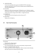
4 Controls and Indicators
4.1 Front Panel Description
1) POWER SWITCH
Turns power on and off.
2) ATTENUATE KEY
Attenuates the output signal by 20 dB.
3) FREQUENCY RANGE SELECTION BUTTON
Selects output frequency range (Hz, KHz, or MHz).
4) DUTY CYCLE KEY
Used to specify duty cycle of a square waveform.
5) FUNCTION SELECTOR BUTTON
Selects sine, square, or triangle waveform.
6) ENTER KEY
Used to confirm frequency or duty cycle entry.
7) SYNC OUTPUT
TTL level square signal output synchronous with frequency of MAIN OUTPUT.
This output is independent of output level and DC offset controls.
8) MAIN OUTPUT
Waveform selected by FUNCTION SELECTOR BUTTONS at a specified frequency
as well as the superimposed DC OFFSET voltage is available at this output.
2
10
5
12
4
7
8
9
1
11
3
6