
User Manual


13
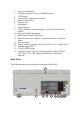
1. Rubber feet
2. Kensington security slot
3. Pass/Fail BNC output
4. LAN interface
5. USB device port (for remote communication)
6. Rear USB host port (for storage to USB flash drives)
7. Main AC power switch
8. Input fuse holder
9. AC line input
10. Carrying handle
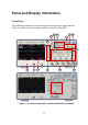
Display Information
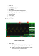
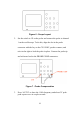
Figure 5 - Display Screen
1. Trigger status
• Armed - The oscilloscope is acquiring pre-trigger data.
All triggers are ignored in this state.
• Ready - All pre-trigger data has been acquired and the
oscilloscope is ready to accept a trigger.
1
2
3
4
5
6
7
8
9
10
11
12
13
14
15
16