
User Manual


Performance Verification Procedure
240
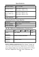
8. Connect calibrator to oscilloscope. If preferred calibrator is
not available, connect alternative equipment as follows:
9. Apply a reference signal. The output level of the DC
positive/negative of calibrator output should be equal to 3
times the volts/div setting of oscilloscope. For example, to
test 10 mV/div in CH1, the output of the calibrator should be
set to +30 mV/-30 mV.
10. Compare the reading of the Vavg value at the bottom of the
screen (real time reading of the input signal) to the amplitude of
your reference signal.
11. The DC gain should always be ≤ 4% for 2 to 5 mV/div and ≤ 3%
for 10 mV to 5 V/div.
−+
−+
−
−
=
∆
∆
=
DMMDMM
peoscilloscopeoscillosco
VV
VV
Vin
Vout
GainDC
In above example, the difference between positive and
negative input value is 60 mV.
12. Select the next volts/div setting.
13. Repeat the above steps for channel 2.
Oscilloscope
DC Power
Supply
DMM