
User guide

15
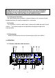
3-2. Operating Instructions
a. Connect the unit up to the AC power.
b. Turn on the unit by pushing in the POWER on-off switch.
c. Set the FUNCTION indicator position to FREQ A and the gate TIME
indicator to the 1 Sec, position.
CAUTION
1. APPLICATION OF INPUT VOLTAGES HIGHER THAN THE LIMITS LISTED IN
THE SPECIFICATIONS SECTION MAY DAMAGE THE COUNTER. BEFORE
APPLYING ANY SIGNAL TO THE INPUTS, MAKE CERTAIN THAT IT DOES NOT
EXCEED THESE SPECIFIED MAXIMUMS.
2. FREQUENCY COUNTER GROUND POINTS ARE CONNECTED DIRECTLY TO
EARTH GROUND. CONNECT GROUND OF THE CIRCUIT UNDER TEST TO
THE FREQUENCY COUNTER GROUND ONLY
3-3. Frequency Measurements
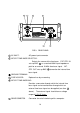
A. INPUT A (0.1 Hz to 100 MHz):
a. Apply the signal to be measured at input A.
b. Set the FUNCTION indicator to FREQ. A
c. Select the resolution using the GATE TIME selector switch.
d. The frequency is indicated on the display. The gate indicator is lit while
the measurement is in progress, and the display is updated at the end of
each measurement interval.
e. Engaging the HOLD switch “freezes” the display at the existing reading.
When HOLD is released, the display is updated and resumes counting.
f. Engage the ATTENUATOR if necessary. When set to x10 (pushed in),
the signal at input A is attenuated by a factor of approximately 10 before it
is applied to the counter. This helps prevent miscounting caused by noisy
or improperly terminated high amplitude signals.
g. Engage the LOW PASS FILTER (LPF) if necessary. When this switch is