
User guide

12
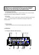
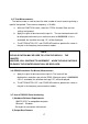
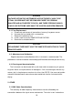
FIG.2 FRONT PANEL
GATE INDICATOR: The gate light, when lit, indicates the main gate is open
and measurement is in progress.
RS-232C INDICATOR: TX (transmitting), RX (receiving) blinking
OVER FLOW INDICATOR: OF is displayed when there is an overflow.
DISPLAY: 9 digit (0.56“) green LED display used for all readings.
NOTE: LAST MEASUREMENT DISPLAY WILL REMAIN FOR 10 SECONDS
AFTER SIGNAL OFF.
UNIT INDICATOR: When lit, indicates that the frequency displayed is in
MHz, KHz, Hz and period is in nano, micro, or milli
(n/u/m) Sec.
HOLD INDICATOR: The HOLD function is engaged the when lit.
INPUT C: Use this input for all frequency measurements above 80
MHz. Female N type connector terminated in 50.
LOW PASS FILTER: With this switch pushed in, the A input is routed through
a low-pass filter with a -3 dB point at approximately 100
KHz. When it is released, the A input is applied directly
to the counter.
ATT. SWITCH: When this switch is set to x10 (pushed in) the A input is
attenuated 10:1 before application to the counter. With
the switch set to x1 (pushed out), the A input signal is
applied unattenuated. The attenuator has no effect on
the C input.
COUPLE. SWITCH: This switch is used to select the input coupling
mode, AC or DC.
INPUT A: Use this input for frequency measurements below 100
MHz and all period measurements. Female BNC
connector. Input impedance is1 M shunted by < 40