Instruction Manual Model 1856D 3.
WARRANTY Warranty service covers a period of one year from the date of original purchase. In case of technical failure within one year, repair service will be provided by our service center or sales outlet free of charge. We charge customers for repairs after the one-year warranty period has expired. We charge for repairs regardless of the warranty period if failure resulted from the user’s negligence, natural disaster or accident.
Introduction Thank you for purchasing our product. Electronic measuring instruments produced by us are high technology products made under strict quality control. We guarantee their exceptional precision and utmost reliability. For proper use of the product, please read this operation manual carefully. Note To maintain the full precision and reliability of this product, use it within the temperature range of 10 C to 35 C (50 oF to 95 oF), and within a humidity of 45% to 85%.
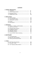
CONTENTS 1. PRODUCT DESCRIPTION 1-1. Introduction ----------------------------------------------------1-2. Technical Specifications -----------------------------------1-3. Equipment Ratings ------------------------------------------1-4. Supplied Accessories ---------------------------------------- (5) (6) (9) (10) 2. INSTALLATION 2-1. Initial Inspection ----------------------------------------------2-2. Connecting AC Power --------------------------------------2-3.
1. PRODUCT DESCRIPTION 1-1. Introduction This reciprocal FREQUENCY COUNTER is a microprocessor-controlled instrument for frequency measurement. Due to uniquely developed LSI circuitry in an expanding/reciprocal system, high accuracy with 9-digit resolution is achieved with a one second gate time. It covers a frequency range of from 0.1 Hz to 3.5 GHz based on a 10 MHz TCO (Temperature Controlled Oscillator).
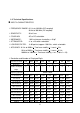
1-2. Technical Specifications INPUT A CHARACTERISTICS FREQUENCY RANGE: 0.1 Hz to 100 MHz (DC coupled) 30 Hz to 100 MHz (AC coupled) SENSITIVITY: 30 mV rms COUPLING: AC or DC selectable. IMPEDANCE: 1 M resistance shunted by < 40 pF ATTENUATOR: x1 or x10 switch selectable LOW PASS FILTER: -3 dB point at approx. 100 KHz, switch selectable ACCURACY: 0.1Hz to 999Hz + Time base stability + 1 count + 1Hz 1KHz to 99KHz + Time base stability + 1 count + 0.
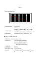
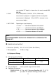
(Table 1) Max. Input Voltage Level MAX INPUT VOLTAGE (ACV & DCV) 300 250 200 150 100 50 25 5 0 100 500 1K 1M 5M 10M 50M 100M FREQUENCY (Hz) FIG. 1 MAX. Input Level. (Input A) PERIOD RANGE: 10 nS to 10 S DISPLAY: n/u/m (nano/micro/milli) Sec. with dec point Accuracy: + Time base stability + 0.3% + 1 count TOTAL RANGE: 10 Hz to 30 MHz CAPACITY: 0 to 999 999 999, RPM RANGE: 600 to 600 x 10 RPM, 6 OVER FLOW : OVER FLOW : “OF” “OF” INPUT C.
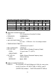
Resolution and Number of Displayed Digits Time Base Selector INT EXT Gate Time 0.01S Number Of 5 6 Displayed Digits Frequency (Input C) 80 MHz-999 MHz 10 KHz 1 KHz 1 GHz-3.7 GHz 100 KHz 10 KHz INT EXT INT 7 7 0.1S 6 1 KHz 10 KHz EXT INT 8 8 1S RESOLUTION 100 Hz 100 Hz 1 KHz 1 KHz EXT 10S 10 Hz 10 Hz 100 Hz 100 Hz 9 1 Hz 10 Hz (Table 2) TIME BASE CHARACTERISTICS TYPE: TCO (Temperature Controlled Oscillator) FREQUENCY: 10.
user selected. OF display is shown when the count exceeds 999 999 999. HOLD: In the FREQUENCY, PERIOD, TOTAL, RPM modes, measurement in progress is stopped; and the last complete measurement is displayed. When HOLD is released, a new measurement begins. GATE TIME: Depending on input frequency < 10 mS----------- Somewhere between 0.9 and 9mS < 0.1 S------------- Somewhere between 9 and 90mS < 1 S----------------Somewhere between 90 and 900mS < 10 S---------------Somewhere between 0.
temperature extremes causing condensation within the instrument. Storage Environment: TEMPERATURE: -20°C to +70°C HUMIDITY: below 85% RH Insulation Category II: Portable equipment of local level. Pollution Degree: Protection to IEC 529: Ordinary 2 Information and specifications are subject to change without notice. Please visit www.bkprecision.com for the most current product information. 1-4.
IN CASE OF 230 V AC, VOLTAGE SELECTOR (on rear panel) SHOULD BE SELECTED TO 230 V POSITION AND THE FUSE SHOULD BE CHANGED ACCORDING TO THE FUSE RATINGS IN THE SPECIFICATIONS. 2-3. Cooling and Ventilation No special cooling and ventilation is required. However, the instrument should be operated where the ambient temperature is maintained. 2-4. Position This instrument is built as a bench-type instrument with rubber feet and tilt stand in place.
FIG.2 FRONT PANEL GATE INDICATOR: The gate light, when lit, indicates the main gate is open and measurement is in progress. RS-232C INDICATOR: TX (transmitting), RX (receiving) blinking OVER FLOW INDICATOR: OF is displayed when there is an overflow. DISPLAY: 9 digit (0.56“) green LED display used for all readings. NOTE: LAST MEASUREMENT DISPLAY WILL REMAIN FOR 10 SECONDS AFTER SIGNAL OFF.
pF. GATE TIME SWITCH: This switch selects the degree of resolution on the display in all modes except TOTAL. HOLD SWITCH: In the HOLD function, the display is held but the counter continues to increment. When HOLD is released, the display is updated and resumes counting. FUNCTION SWITCH: This selects the desired operating mode. a. FREQ. A: When this mode is selected, the counter reads the frequency of the input at A. Resolution is selected using the GATE TIME. b. FREQ.
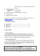
5 6 2 3 1 FIG.3 AC INLET: 4 REAR PANEL AC power input connector INT/EXT TIME BASE SELECTOR: Selects the source of the time base. sets up BNC EXT.STD.
3-2. Operating Instructions a. Connect the unit up to the AC power. b. Turn on the unit by pushing in the POWER on-off switch. c. Set the FUNCTION indicator position to FREQ A and the gate TIME indicator to the 1 Sec, position. CAUTION 1. APPLICATION OF INPUT VOLTAGES HIGHER THAN THE LIMITS LISTED IN THE SPECIFICATIONS SECTION MAY DAMAGE THE COUNTER. BEFORE APPLYING ANY SIGNAL TO THE INPUTS, MAKE CERTAIN THAT IT DOES NOT EXCEED THESE SPECIFIED MAXIMUMS. 2.
pushed in, the signal at input A is routed through a low pass filter (-3 dB point at approximately 100 KHz) before it is applied to the counter. This helps eliminate counting errors in low frequency measurements by minimizing effects of high frequency noise that may accompany the signal. h. When making measurements near the lower cut-off frequency of input A (10 Hz or less), use DC coupling (Push in the DC COUPLING switch). B. INPUT C (80 MHz to 3.
3-5. Total Measurements The totalize mode is used to count the total number of events occurring during a specific time period. The maximum frequency is 30 MHz. a. With the FUNCTION switch, select the TOTAL A mode. Gate and unit settings are ignored. b. Apply the signal to be measured at input A. The accumulated counts will be displayed continuously to a maximum count of 999999999. If this is exceeded, the overflow message, OF, will be displayed. c.
(1) Baud rate : 9600BPS 1 start bit (0) 8 data bit 1 stop bit (1) NONE PARITY (2) To Frequency counter Command Parameter 'H' : HOLD '0' : OFF Terminate Code '1' : ON CR (0DH) '2' : TOGGLE 'G' : GATE '0' : 0.01 SEC '1' : 0.1 SEC CR (0DH) '2' : 1 SEC '3' : 10 SEC 'D' : DATA REQUEST DON'T CARE CR(0DH) 'F' : FUNCTION SET N* CR(0DH) 'R' : REMOTE '0' : OFF CR(0DH) '1' : ON N*= 0 1 2 3 4 5 6 7 3.
WARNING VOLTAGES WITHIN THIS INSTRUMENT ARE SUFFICIENTLY HIGH TO BE LETHAL. COVERS MUST NOT BE REMOVED EXCEPT BY PERSONS QUALIFIED AND AUTHORIZED TO DO SO, AND THESE PERSONS SHOULD ALWAYS USE EXTREME CARE ONCE THE COVERS HAVE BEEN REMOVED. 4-1. Fuse Replacement a. Disconnect and remove all connections from any live power source. b. Unscrew the fuse holder with a screwdriver. c. Remove the defective fuse. d. Install a new fuse of the SAME SIZE AND RATING. e. Screw the fuse holder back in.
standing waves and cable shunt capacitance. Waves propagating along a transmission line will be reflected at its ends if the line is not terminated in its characteristic impedance. These reflections will set up standing waves in the line, which may cause damage to the signal source or produce inaccurate measurements. This effect increases as the cable length reaches one-fourth of the wavelength for the frequency being measured.
DO NOT USE A 10:1 PROBE WITH THE INPUT C. THESE PROBES ARE DESIGNED WITH A 10:1 ATTENUATION FOR AN INSTRUMENT WITH AN INPUT RESISTANCE OF 1 M . THE 50 TERMINATION OF INPUT C WOULD RESULT IN UNACCEPTABLY HIGH ATTENUATION. 5-3. Line Frequency Measurements When making line frequency measurements, use of the LOW PASS FILTER, the ATTENUATOR, and/or the 10:1 probe is recommended. WARNING USE CAUTION WHEN MEASURING THE LINE FREQUENCY OF AN AC OUTLET. USE THE PROBE TIP ONLY, AND MEASURE BOTH SIDES OF THE LINE.
Limited One-Year Warranty B&K Precision Corp. warrants to the original purchaser that its product and the component parts thereof, will be free from defects in workmanship and materials for a period of one year from the data of purchase. B&K Precision Corp. will, without charge, repair or replace, at its’ option, defective product or component parts. Returned product must be accompanied by proof of the purchase date in the form a sales receipt. To obtain warranty coverage in the U.S.A.
Exclusions: This warranty does not apply in the event of misuse or abuse of the product or as a result of unauthorized alternations or repairs. It is void if the serial number is alternated, defaced or removed. B&K Precision Corp. shall not be liable for any consequential damages, including without limitation damages resulting from loss of use. Some states do not allow limitation of incidental or consequential damages, so the above limitation or exclusion may not apply to you.
rate repair charge includes return shipping to locations in North America. For overnight shipments and non-North America shipping fees contact B&K Precision Corp.. B&K Precision Corp. 22820 Savi Ranch Parkway Yorba Linda, CA 92887 Phone: 714- 921-9095 Facsimile: 714-921-6422 Email: service@bkprecision.com Include with the instrument your complete return shipping address, contact name, phone number and description of problem. v4.8.